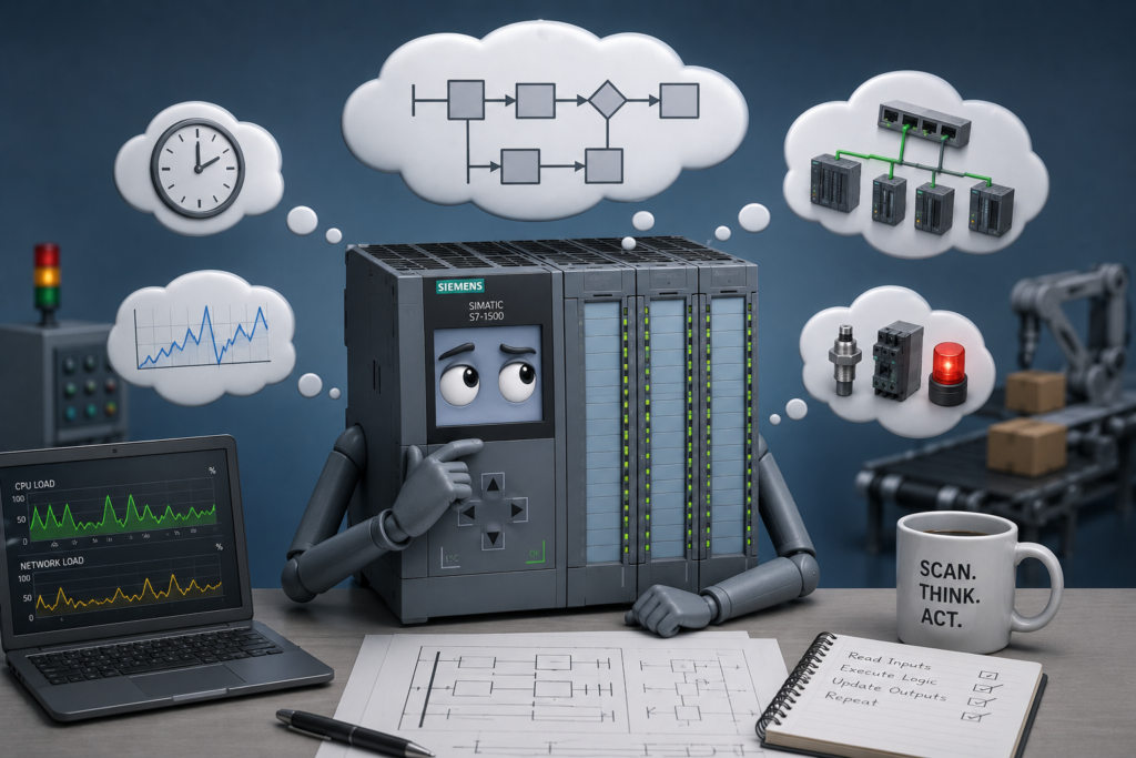
Good PLC programming is not simply about making a machine operate correctly once.
The real challenge is making it behave predictably during startup, normal production, communication interruptions, operator mistakes and unexpected field conditions.
A program may work perfectly during commissioning when every sensor is forced in the expected order. That does not mean it will remain reliable when several devices change state together, remote I/O is delayed or equipment restarts after a power failure.
Professional PLC logic should produce a clear and repeatable result even when the surrounding industrial process is not perfectly stable.
This is the goal of deterministic PLC programming.
What Does Deterministic Mean in PLC Programming?
A deterministic control system behaves consistently when given the same relevant conditions.
The programmer should be able to answer questions such as:
- What happens after power is restored?
- What happens when two commands arrive together?
- What happens if communication disappears?
- What happens if a sensor changes during a sequence transition?
- What happens when an operator presses RESET while the fault is still active?
- What happens when the PLC returns to RUN after an interruption?
The answer should not depend on accidental network order, unclear latch behaviour or whichever instruction happens to execute last.
This does not mean every industrial event occurs at exactly the same time. Real machines contain variable delays, mechanical movement and asynchronous communication.
Deterministic programming means designing the logic so those variations do not create an undefined result.
Define Startup States Explicitly
Startup is one of the most common sources of unpredictable machine behaviour.
After power is restored, different parts of the system become available at different times:
- The PLC CPU enters RUN.
- Remote I/O reconnects.
- Drives complete initialization.
- Smart instruments begin sending valid values.
- Pneumatic pressure builds.
- Safety devices reset.
- Mechanical components remain in their previous positions.
The program should not assume that everything is immediately ready.
A reliable startup sequence can include defined states such as:
- PLC initialization
- Communication validation
- Safety-system validation
- Field-device initialization
- Position verification
- Ready for reset
- Ready for automatic operation
During initialization, outputs should remain in known safe states unless a particular device requires controlled recovery.
A startup-complete bit should become true only after all required conditions have been verified for an appropriate period.
Do Not Depend on Retained Values Alone
Retentive memory can preserve sequence steps, counters and operator settings after power loss. This is useful, but it can also create dangerous restart conditions.
Suppose the PLC retained:
- Sequence step 12
- Motor command active
- Automatic mode selected
- Valve-open request active
After power returns, the physical machine may no longer match those stored states.
A cylinder may have moved because air pressure disappeared. A contactor may have released. A product may have been removed manually.
The controller should validate the physical process before continuing from a retained sequence step.
In many applications, the safest approach is to return to a defined recovery state and require position confirmation before resuming operation.
Avoid Ambiguous Transitions
A sequence transition should have one clear meaning.
Poorly structured logic may allow several transitions to become true during the same scan. The resulting step depends on network order or which assignment executes last.
For example, a sequence step might contain:
- Advance if the cylinder is extended.
- Return to home if automatic mode is removed.
- Enter fault if the movement timer expires.
- Skip forward if bypass mode is active.
What happens when the cylinder reaches its sensor during the same scan that the timeout expires?
The program should define the intended priority.
One possible structure is:
- Safety fault
- Process fault
- Stop or abort request
- Successful transition
- Normal waiting state
Only one transition should be accepted during each evaluation.
State-machine logic is often easier to understand when the transition priority is written explicitly rather than distributed across several ladder networks.
Use One Owner for Each Command
Unpredictable logic frequently comes from writing to the same tag in multiple places.
A motor command might be:
- Set in automatic sequence logic
- Reset in fault logic
- Set in manual controls
- Reset in safety logic
- Modified by HMI commands
- Forced during commissioning
The final state may depend on execution order.
A more deterministic design calculates separate requests:
Auto_Run_RequestManual_Run_RequestMaintenance_Run_RequestStop_RequestFault_ActiveSafety_Healthy
The final motor command is then assigned once:
Motor_Run :=
    Safety_Healthy
    AND NOT Fault_Active
    AND NOT Stop_Request
    AND (Auto_Run_Request OR Manual_Run_Request);
This makes the priority visible.
Safety and faults block the command regardless of which operating mode requested it.
Define Start and Stop Priority
Start and stop commands can occur together.
An operator may press both buttons. An HMI command may arrive while a field stop input is changing. An automatic sequence may request a start at the same time an interlock disappears.
The program must decide what wins.
In most industrial systems:
- Stop overrides start.
- Safety overrides every normal command.
- An active fault prevents reset.
- A reset clears a fault only after its original cause is gone.
Do not rely on the order of two set and reset instructions to establish this behaviour accidentally.
Write the priority deliberately.
Validate Interlocks Properly
An interlock should reflect the real condition required for safe operation.
It should also be evaluated with awareness of timing.
Consider a motor that requires:
- Safety circuit healthy
- Overload healthy
- Drive communication available
- Drive ready
- Process valve open
- Minimum pressure available
Some conditions may update locally, while others arrive through remote I/O or communication telegrams.
Requiring every condition to become true in one scan may cause intermittent startup failures.
A startup permissive may instead require all conditions to remain healthy continuously for a short validation period.
However, removing an operating permissive may need a faster reaction than establishing it.
For example:
- Pressure must be healthy for two seconds before startup.
- Genuine low pressure stops the motor after 200 milliseconds.
- Safety loss stops it immediately through the appropriate safety system.
Different timing can be appropriate for enabling and disabling the same process condition.
Separate Transitional States From Faults
A machine moving between two positions often passes through a state where neither limit switch is active.
That may be completely normal.
Suppose a valve has:
- Closed-position sensor
- Open-position sensor
While the valve is moving, both sensors may be false.
The program should distinguish between:
- Valve commanded closed
- Valve opening
- Valve confirmed open
- Valve closing
- Valve confirmed closed
- Movement timeout
- Contradictory sensor fault
Without explicit movement states, the temporary absence of both sensors may be interpreted as a fault.
A deterministic sequence knows which intermediate conditions are expected and how long they are allowed to continue.
Isolate Asynchronous Data
Signals from different devices do not necessarily update together.
A PLC may receive:
- Local digital inputs every scan
- Remote PROFINET inputs every few milliseconds
- VFD data through a separate communication cycle
- Modbus values every few hundred milliseconds
- HMI commands asynchronously
A logic network that directly combines all these values may occasionally process a mixture of old and new information.
For related communication data, use a controlled update method.
One approach is:
- Receive the complete device data.
- Confirm communication is healthy.
- Confirm the data record is valid.
- Copy it into a local program structure.
- Process the local snapshot during the control cycle.
This helps prevent the program from using partially updated information.
Never Trust Process Data Without Quality Information
A communication value may remain at its last valid number after the connection fails.
A pressure value can still show 5.1 bar even though it has not updated for several minutes.
Deterministic control requires both:
- The process value
- Evidence that the value is current and valid
Useful checks include:
- Device-connected bit
- Data-valid status
- Communication watchdog
- Update counter
- Timestamp
- Signal-quality code
- Module diagnostic status
When data becomes stale, the program should enter a defined response.
That response might be:
- Stop the affected equipment
- Use a redundant measurement
- Enter a limited operating mode
- Hold the last value temporarily
- Generate an alarm
- Require operator intervention
The behaviour should be designed in advance rather than discovered during a network failure.
Minimize Hidden Latches
Latches are useful for alarms, sequence memory and event capture. They become dangerous when their set and reset conditions are spread throughout the program.
A hidden latch can remain active long after the original reason disappeared.
Common problems include:
- Fault resets immediately because the active condition still exists.
- A retained latch restarts equipment after power restoration.
- A command remains set after changing operating mode.
- Several networks set and reset the same bit.
- An HMI button clears a latch without confirming safe conditions.
Each latch should have:
- A clear reason for being set
- A visible reset condition
- Defined priority
- Known retentive or non-retentive behaviour
- A documented startup state
For fault memory, the active fault should normally take priority over the reset command:
IF Fault_Condition THEN
    Fault_Latched := TRUE;
ELSIF Reset_Request THEN
    Fault_Latched := FALSE;
END_IF;
This prevents an operator from clearing a fault that is still present.
Use Handshakes Between Devices
Timing assumptions are unreliable when two controllers, robots or machines must coordinate.
A simple command bit may be missed if it exists for only one communication cycle.
A handshake is more dependable:
- Controller A sets
Request. - Controller B receives it and sets
Acknowledge. - Controller B performs the requested action.
- Controller B sets
Complete. - Controller A removes
Request. - Controller B removes
AcknowledgeandComplete.
Each stage remains active until the other side confirms receipt.
This design tolerates different scan times and communication update rates.
Timeouts should also be included so the sequence does not wait forever when a device fails to respond.
Make Recovery Behaviour Explicit
A strong control program does not only detect faults. It also defines how the machine recovers.
After a fault is cleared, decide whether the system should:
- Return to idle
- Repeat the interrupted step
- Move equipment to home positions
- Resume from the previous step
- Require manual recovery
- Discard the current production cycle
- Perform a controlled shutdown
Automatic recovery is not always the safest option.
For example, restarting a conveyor from a retained command may be unacceptable if personnel could have entered the area during the interruption.
Recovery logic should verify:
- Safety conditions
- Device communication
- Physical positions
- Process readiness
- Valid sequence state
- Operator authorization
A reset should not simply remove an alarm. It should place the system into a known and recoverable state.
Use Timeouts for Every Expected Response
Whenever the PLC commands an external action, it should know how long that action is allowed to take.
Examples include:
- Contactor feedback
- Valve movement
- Cylinder position
- Drive-ready response
- Robot acknowledgement
- Remote controller handshake
- Communication reconnection
The timer should begin when the command is issued and stop when the expected confirmation arrives.
If the response does not occur in time, generate a specific fault:
Valve V12 failed to reach open position within 4 seconds.
This is much more useful than a general sequence error.
Timeout values should be based on realistic worst-case machine behaviour, including temperature, load and supply variations.
Use First-Out Fault Capture
Several interlocks may disappear after one initial problem stops the machine.
For example, low pressure may stop a pump. The stopped pump then removes flow, drive-running feedback and downstream process conditions.
By the time the operator checks the HMI, five alarms are active.
Only the first one explains the original failure.
A first-out diagnostic system records:
- First condition that failed
- Date and time
- Sequence step
- Relevant process values
- Command states
- Communication status
This makes troubleshooting repeatable and prevents secondary alarms from hiding the real cause.
Test Abnormal Conditions Deliberately
A program is not fully tested when it works only under the expected sequence.
Commissioning should also test:
- Power loss during operation
- Communication interruption
- Remote I/O reconnection
- Sensor failure
- Conflicting start and stop commands
- Reset while the fault remains active
- Slow actuator response
- Missing feedback
- Operator mode changes
- Unexpected sequence order
- Several interlocks changing together
The purpose is not to create every imaginable failure.
It is to verify that the system always moves toward a known state rather than becoming stuck, skipping steps or issuing contradictory commands.
Keep the Logic Understandable
Complexity is not the same as quality.
A program with hundreds of scattered latches and indirect conditions may technically work, but it becomes difficult to predict and maintain.
Strong PLC programs often use:
- Clear sequence states
- Centralized output commands
- Explicit priorities
- Descriptive tag names
- Consistent function blocks
- Defined data ownership
- Meaningful alarms
- Documented recovery paths
A technician should be able to determine:
- Why an output is on
- Why it is off
- What condition is missing
- Which fault occurred first
- What must happen before restart
Predictability is more valuable than cleverness.
Final Thoughts
Deterministic PLC programming means designing logic that behaves consistently even when the industrial environment does not.
Network updates arrive at different times. Devices start at different speeds. Sensors change during scan execution. Communication values become stale. Operators issue commands at unexpected moments.
The program cannot prevent all of those conditions.
It can prevent them from producing an ambiguous result.
Define startup states, establish command priorities, isolate asynchronous data, validate interlocks and make fault recovery deliberate.
The strongest control system is not the one containing the most instructions.
It is the one whose behaviour remains understandable when the plant stops behaving perfectly.