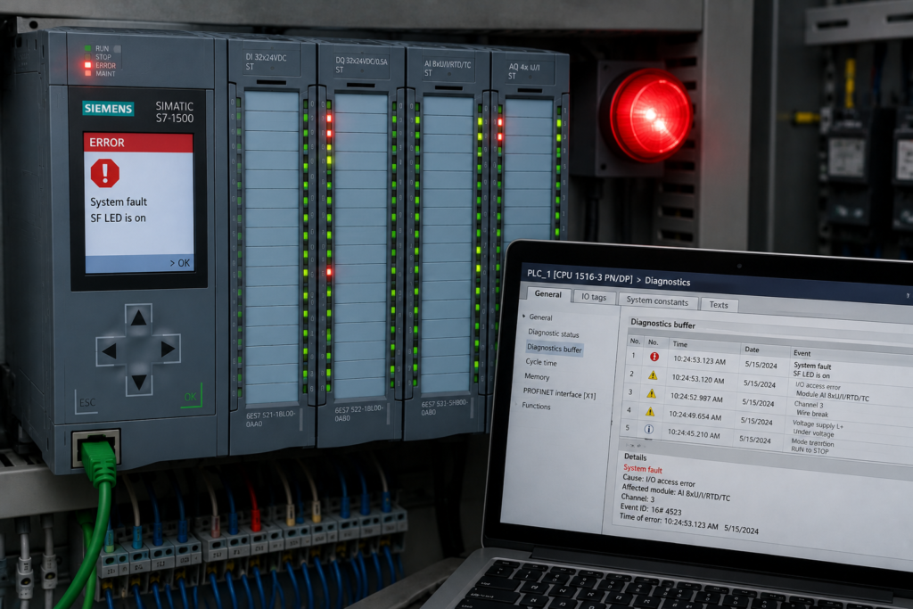
Intermittent PLC faults are rarely difficult because the controller provides no information. They are difficult because the evidence disappears before anyone begins troubleshooting.
A machine fails during startup, enters an unexpected sequence state or refuses to restart after an alarm. Minutes later, every sensor looks healthy, communication has recovered and the HMI shows no obvious reason for the failure.
Restarting the machine may clear the problem, but it also destroys valuable diagnostic evidence.
An Advanced PLC Fault and Logic Recovery Suite is designed to capture that evidence, recreate unstable timing conditions and verify that the machine always returns to a safe, predictable state.
Its purpose is not simply to reset faults faster. It is to determine why the logic failed, what happened during recovery and whether restarting the process is genuinely safe.
Why Recovery Logic Needs Dedicated Testing
Many PLC programs receive most of their testing during normal operation.
The commissioning engineer verifies that:
- Inputs operate correctly
- Motors start and stop
- Valves reach their commanded positions
- Sequences advance normally
- Alarms appear when expected
Far less attention is often given to abnormal recovery.
What happens when:
- Power fails halfway through a movement?
- A remote I/O rack reconnects after the PLC has entered RUN?
- A drive becomes ready later than the rest of the machine?
- An operator presses RESET while an interlock is still unstable?
- Communication returns with old process data?
- Several fault conditions clear during different scans?
These situations create some of the most dangerous and expensive automation problems.
A system may detect a fault correctly but recover from it incorrectly.
Core Purpose of the Recovery Suite
A practical recovery suite should help engineers:
- Diagnose intermittent sequence failures
- Record the order of asynchronous events
- Reproduce startup timing variations
- Validate fault-reset logic
- Confirm recovery-state transitions
- Detect stale or invalid field data
- Prevent unexpected automatic restarts
- Verify that interlocks return in a controlled order
The suite should provide evidence from before, during and after the fault.
A normal watch table shows only the present state. Recovery diagnostics should show the sequence that led to it.
Intermittent Startup Simulation
Startup timing is rarely identical on every attempt.
One time, the safety system may reset first. On another attempt, remote I/O may establish communication before the drives complete initialization. Pneumatic pressure may build quickly when the system is warm and more slowly after a long shutdown.
The PLC program should tolerate these differences without entering contradictory states.
A startup simulator can introduce controlled delays into conditions such as:
- Safety healthy
- Remote I/O available
- Drive ready
- Air pressure healthy
- Fieldbus communication established
- Valve position confirmed
- Sensor data valid
- Operator start request
Each condition can be delayed, removed temporarily or activated in a different order.
The goal is to confirm that the machine waits correctly rather than assuming a fixed startup sequence.
Explicit Startup States
A reliable machine should not move directly from power-up to automatic operation.
Useful startup states may include:
- Initialization
Internal tags, timers and diagnostic structures are prepared. - Communication check
Remote I/O, drives and connected controllers must establish valid communication. - Data validation
Process values must be confirmed as current rather than merely retaining old numbers. - Safety verification
Required safety conditions must be healthy. - Position verification
Valves, cylinders and mechanisms must be in known or recoverable positions. - Reset permitted
The system may accept an operator reset. - Ready for operation
Automatic or manual movement may begin.
These states make startup behaviour visible and prevent equipment from running while the system is only partially initialized.
Restart Sequence Validation
Restart logic should be tested after several different interruptions:
- Normal stop
- Emergency stop
- Overload trip
- Communication failure
- PLC power loss
- Field power loss
- Drive fault
- Sequence timeout
- Operator abort
Each event may require a different recovery path.
For example, a normal stop may allow the sequence to continue from its current position. After an emergency stop, the machine may need to return to a recovery state and require manual confirmation.
After a PLC power failure, retained sequence data must be compared with actual field positions before operation resumes.
The correct restart method depends on the process, but it should always be intentional.
Retained Memory and Physical Reality
Retentive PLC memory can preserve:
- Sequence step
- Production counters
- Active mode
- Setpoints
- Internal commands
- Fault history
This is useful, but retained logic does not guarantee that the machine remained in the same physical condition.
During power loss:
- Pneumatic cylinders may move
- Valves may spring closed
- Contactors release
- Drives lose torque
- Products are removed manually
- Tank levels continue changing
- Pressure decays
A retained sequence step may therefore describe a machine state that no longer exists.
The recovery suite should compare stored information with field feedback before allowing the program to continue.
When the physical and retained states disagree, the machine should enter a defined recovery mode rather than blindly resuming the interrupted step.
Fault-Recovery Sequencing
A fault reset should not simply clear an alarm bit.
A complete recovery sequence may need to:
- Confirm that the original fault has disappeared.
- Verify safety conditions.
- Confirm communication with affected devices.
- Validate sensor and analog data.
- Remove unsafe commands.
- Return mechanisms to known positions.
- Re-establish sequence ownership.
- Request operator acknowledgement.
- Permit a controlled restart.
Skipping these checks may cause the machine to restart into the same fault or move unexpectedly.
For instance, resetting a valve-position timeout should not immediately issue the same movement command if the valve feedback remains invalid.
Active Fault Must Override Reset
One common source of unstable recovery is a reset request competing with an active fault condition.
Suppose the operator holds the reset button while a pressure interlock repeatedly changes between healthy and unhealthy.
Without clear priority, the alarm may:
- Reset for one scan
- Set again on the next scan
- Allow a sequence transition briefly
- Reappear after equipment begins moving
A deterministic structure gives the active fault priority:
IF Fault_Condition THEN
    Fault_Latched := TRUE;
ELSIF Reset_Request AND Reset_Conditions_Valid THEN
    Fault_Latched := FALSE;
END_IF;
The reset succeeds only after the process is genuinely ready.
Asynchronous Interlock Restoration
Interlocks rarely recover at exactly the same time.
After a fault, the PLC may see:
- Safety relay healthy first
- Drive communication second
- Motor-ready signal third
- Process pressure fourth
- Valve confirmation last
If the program reacts immediately to each returning bit, it may move through several unstable intermediate states.
A stronger design combines the required conditions into a recovery permissive and validates that permissive for a defined period.
For example:
All required restart conditions must remain continuously healthy for two seconds before reset is accepted.
This removes brief communication changes and contact bounce from the recovery decision.
The delay should be appropriate for the process. It should not be used to hide a genuinely unstable field condition.
Race Conditions During Recovery
Recovery logic is particularly vulnerable to race conditions because several events may occur together.
Examples include:
- Fault clears while RESET is pressed
- Communication returns while a timeout is active
- A sequence-complete input appears during an abort request
- Automatic mode is selected as the machine reaches its home position
- A drive-ready bit appears during safety reset
- Two sequence transitions become valid in one scan
Each combination should have a clearly defined outcome.
The result must not depend on whichever ladder network happens to execute last.
Useful priority rules include:
- Safety failure
- Active process fault
- Stop or abort request
- Recovery command
- Normal sequence transition
Only one state transition should be accepted during each sequence evaluation.
Recovery-State Timing Analysis
A timing analyzer should record the complete recovery path.
Useful signals include:
- Original fault condition
- Latched fault
- Reset request
- Safety status
- Communication status
- Interlock states
- Current recovery step
- Previous recovery step
- Output commands
- Device feedback
- State-transition reason
- PLC cycle time
Timestamping these changes allows engineers to see whether the recovery failed because of a missing condition, delayed communication or incorrect program order.
Without timestamps, several events may appear to have happened together even though they were separated by multiple PLC scans.
First-Out Fault Recording
When one event stops a machine, several secondary alarms often follow.
For example:
- Drive communication fails.
- Motor stops.
- Flow disappears.
- Pressure falls.
- Downstream equipment loses its ready signal.
- Sequence timeout activates.
By the time the operator checks the HMI, five alarms may be present.
Only the first one identifies the original problem.
A first-out fault recorder should capture:
- First failed condition
- Date and time
- Sequence step
- Active command
- Relevant analog values
- Communication status
- Operating mode
- CPU scan time
This information should remain available after the secondary alarms appear.
Sequence History Buffer
A useful recovery suite should retain several previous sequence states rather than only the current one.
A history buffer might record:
- Step number
- Entry timestamp
- Exit timestamp
- Transition reason
- Fault active at transition
- Operator command
- Relevant device status
For example:
14:25:17.240 — Step 20: Clamp closing
14:25:18.105 — Step 21: Waiting for clamp confirmation
14:25:20.105 — Fault: Clamp close timeout
14:25:20.110 — Recovery Step 900: Motion inhibited
This is much more useful than simply seeing Current_Step = 900.
Stale-Data Checks During Recovery
Communication recovery does not always mean process data is immediately trustworthy.
A remote device may reconnect while still reporting:
- Old retained values
- Initialization defaults
- Invalid quality
- Zeroed data
- Values from before the interruption
The recovery logic should verify that data is updating again.
Useful methods include:
- Incrementing heartbeat counters
- Data-valid bits
- Device status words
- Timestamps
- Change counters
- Plausibility checks
- Minimum stabilization periods
For example, a pressure transmitter may need to provide valid updates for several communication cycles before its value is accepted as a restart permissive.
Manual, Automatic and Recovery Modes
Recovery commands should not be mixed invisibly with normal operating logic.
A clear program may distinguish between:
- Automatic mode
- Manual mode
- Maintenance mode
- Recovery mode
- Faulted state
- Safe stopped state
During recovery mode, only approved actions should be possible.
For example, technicians may be allowed to:
- Retract one cylinder
- Close a valve
- Jog a conveyor slowly
- Release trapped material
- Return the sequence to home
Normal automatic transitions should remain disabled until recovery is complete.
This prevents manual troubleshooting commands from accidentally starting the automatic sequence.
Verify Safe Restart Conditions
Before enabling operation, the program should verify relevant conditions such as:
- Safety system reset and healthy
- No active emergency-stop condition
- Fault cause removed
- Remote I/O connected
- Device communication valid
- Drives ready
- Actuators in accepted positions
- Analog values current and plausible
- No conflicting manual command
- Sequence state known
- Operator restart requested
The exact list depends on the machine risk assessment and operating process.
A single generic System_Healthy bit may be convenient, but detailed internal diagnostics should still show why restart is blocked.
Recommended Workflow
1. Simulate intermittent startup conditions
Delay devices and permissives in different combinations. Confirm that the machine waits safely and produces meaningful diagnostics.
2. Validate restart timing
Test restart after each major fault category. Record how long interlocks, communication and feedback signals take to recover.
3. Analyze asynchronous transitions
Observe what happens when reset, communication recovery and sensor changes occur in different PLC scans.
4. Confirm deterministic recovery
Repeat each test several times with different timings. The final machine state should remain consistent.
5. Verify safe restart conditions
Confirm that the system cannot resume automatic operation until all required recovery checks are complete.
Expected Benefits
A structured fault and recovery suite can provide:
- Fewer intermittent startup failures
- Safer restart behaviour
- Faster root-cause identification
- Better first-out fault information
- Reduced unnecessary PLC modifications
- More stable interlock recovery
- Improved operator guidance
- Clearer sequence diagnostics
- Predictable plant behaviour after faults
It also reduces the temptation to solve every intermittent problem by adding another timer.
Timers may hide symptoms temporarily, but they do not replace a clearly designed recovery sequence.
Keep Diagnostic Tools Separate and Controlled
Test functions that simulate communication delays, missing sensors or race conditions can be valuable, but they must not remain casually accessible during normal production.
The suite should use:
- Dedicated commissioning mode
- Controlled user access
- Clear simulation indicators
- Automatic test reset
- Logged test activation
- Safe default values
- Documented disabling procedure
No simulated signal should be mistaken for real process feedback.
Diagnostic logic should reveal machine behaviour without creating a new source of uncertainty.
Final Thoughts
Reliable PLC systems are judged not only by how they run when everything is healthy, but also by how they behave when something goes wrong.
A strong recovery design captures the first fault, validates returning interlocks, rejects stale data and guides the machine toward a known state.
It does not assume that communication, sensors and actuators recover simultaneously. It expects timing variation and handles it deliberately.
The objective is not to restart the machine as quickly as possible.
The objective is to restart it only when the program knows where the machine is, why it stopped and what will happen next.