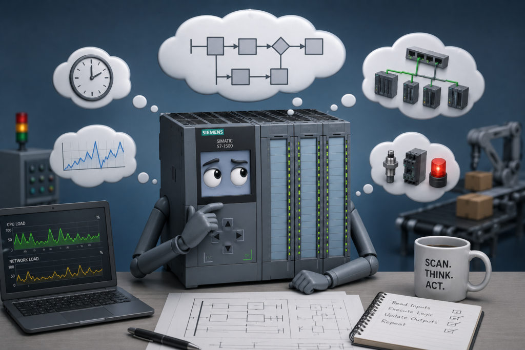
There is one rule every PLC programmer and commissioning engineer eventually learns:
The logic may be correct. The timing may not be.
A PLC program can compile successfully, download without warnings and perform perfectly during simulation. Every contact, timer, comparison and sequence transition may appear correct.
Then the machine enters production and behaves differently.
A motor occasionally fails to start. A sequence enters the wrong step. A sensor transition is missed. A fault appears once every few hundred cycles. Restarting the machine temporarily solves the problem.
These failures are often blamed on defective hardware, bad sensors or incorrect programming. Sometimes those explanations are right. In many cases, however, the actual problem is execution timing.
A PLC Does Not Observe the Process Continuously
A PLC works cyclically.
A simplified scan normally includes:
- Reading input states
- Executing the program
- Updating outputs
- Processing communication and diagnostics
- Repeating the cycle
This happens quickly, often within a few milliseconds, but it is not continuous.
A sensor can change immediately after the PLC reads its inputs. The program may not see that new state until the following scan.
A remote I/O value may arrive after the relevant logic has already executed. An HMI command may be received between two task cycles. An output command may be calculated now but transferred to the physical output later.
These delays are usually small. Small does not mean irrelevant.
Correct Boolean Logic Is Not Enough
Consider a motor that should start when two permissives are true:
Motor_Run := Start_Request AND Drive_Ready;The expression is perfectly valid.
However, suppose the start request arrives from the HMI while the drive-ready status is updating through PROFINET.
During one scan, the PLC may see:
Start_Request = TRUE
Drive_Ready = FALSE
One scan later:
Start_Request = FALSE
Drive_Ready = TRUE
Both conditions occurred, but they were never simultaneously true inside the PLC program.
The motor does not start.
From the operator’s perspective, the start button was pressed while the drive showed ready. From the PLC’s perspective, the two signals never overlapped.
The Boolean logic was correct. The timing assumption was not.
Remote I/O Makes Timing More Complicated
Signals connected to remote I/O must travel through several stages:
- Sensor response
- Input-module filtering
- Remote station processing
- Network transmission
- CPU data update
- PLC task execution
Related signals may also arrive through different paths.
One sensor may be connected directly to the PLC rack, while another comes from a remote PROFINET station. Even when both sensors change physically at nearly the same time, the local signal may become visible several scans earlier.
The program can briefly process combinations that do not represent a stable physical state.
This commonly causes:
- Startup faults
- Sequence mismatches
- Unexpected interlocks
- Missed transitions
- Inconsistent restart behaviour
The solution is rarely to assume that every signal will update together. Logic should be designed to tolerate normal timing differences.
HMI Values Are Not Live Scan-Cycle Evidence
The HMI may update once every few hundred milliseconds while the PLC completes dozens of scans during that period.
A permissive can disappear, stop the motor and recover before the HMI requests its next update.
The operator may continue seeing a green Ready indication even though the PLC already processed a brief loss of readiness.
Likewise, a one-scan pulse may perform an important action without ever appearing on the screen.
This is why an HMI should not be treated as a perfect recording of PLC execution.
For timing-related faults, use:
- PLC traces
- Event counters
- Latched diagnostic bits
- First-out fault capture
- Sequence history
- Timestamps
The HMI shows what it managed to sample. A trace shows what the controller actually processed.
Program Order Also Matters
PLC instructions normally execute in a defined order.
If several networks write to the same tag, the final result may depend on which instruction executes last.
For example:
Network 1:
Start condition → Set Motor_Command

Network 12:
Stop condition → Reset Motor_Command
When both conditions are true during the same scan, the reset normally wins because it executes later.
That may be the correct priority—but only if it was intentional.
Scattered set and reset instructions create logic that is difficult to predict. A stronger design calculates individual requests and assigns the final output once:
Motor_Command :=
    Safety_Healthy
    AND Motor_Permissive
    AND NOT Stop_Required
    AND (Automatic_Request OR Manual_Request);
The priority is now visible. Stop and safety conditions override the operating requests regardless of scan order elsewhere in the program.
Timing Problems Often Appear During Startup
Startup is especially vulnerable because many devices are becoming ready at different speeds.
After power restoration:
- The PLC may enter RUN first.
- Remote I/O may still be reconnecting.
- Drives may be initializing.
- Analog instruments may still contain invalid data.
- Pneumatic pressure may still be building.
- Safety devices may require resetting.
- Mechanical equipment may not match retained sequence states.
If the program evaluates all startup conditions immediately, it may create faults before the field equipment has finished initializing.
A deterministic startup sequence should distinguish between:
- Initializing
- Connected
- Data valid
- Ready
- Faulted
A device that is still starting is not necessarily faulty.
Analog Filtering Can Hide Timing Problems
Filtering makes noisy analog values easier to use, but it also delays them.
A pressure transmitter may physically drop below the shutdown level while the filtered PLC value remains above the threshold for several seconds.
The interlock activates late even though its comparison instruction is correct.
Multiple delays may exist in the same measurement chain:
- Sensor response
- Transmitter damping
- Module filtering
- PLC filtering
- Network delay
- HMI refresh time
The displayed value can look smooth and stable while the real process has already changed.
During commissioning, compare raw and filtered values on the same trace. Filtering should remove noise, not process visibility.
Design for Deterministic Behaviour
Professional PLC programming means producing predictable results even when field timing varies.
Useful principles include:
Define clear startup states
Do not allow automatic operation until communication, safety, field positions and data validity have been confirmed.
Use one writer per command
Calculate the final command in one location rather than setting and resetting it throughout the program.
Define priorities explicitly
Decide what happens when start and stop, fault and reset, or several transitions occur together.
Validate unstable conditions
Require important permissives to remain healthy for an appropriate period before startup.
Use handshakes
When communicating between controllers, robots or drives, use request, acknowledge and complete signals rather than short pulses.
Monitor data quality
Do not trust a process value simply because it still contains a reasonable number. Check communication health, update counters and validity information.
Record the first event
Secondary alarms often hide the original fault. Capture the first failed condition, sequence step and relevant process values.
Verify recovery behaviour
A reset should return the machine to a known state. It should not simply clear an alarm and reissue the same unsafe command.
Troubleshoot the Timeline, Not Just the Final State
When an intermittent failure occurs, the final state rarely explains the complete event.
Instead of asking only:
- Is the input currently true?
- Is the motor command currently active?
- Is communication currently healthy?
Ask:
- Which signal changed first?
- How long was it active?
- Which task processed it?
- Was the value local or remote?
- Did another network overwrite the command?
- Was the displayed value stale?
- What was the maximum scan time?
- Which interlock failed first?
A PLC trace containing raw inputs, processed conditions, sequence states and output commands can reveal more in a few seconds than hours of watching ladder logic online.
Final Thoughts
Industrial PLC failures often originate from timing rather than programming syntax.
The controller may execute every instruction exactly as written while still producing an unexpected machine response. Inputs update at different moments, network data arrives asynchronously, analog filters create delay and program order determines which command wins.
That leads to the non-negotiable rule:
The logic may be correct. The timing may not be.
Reliable PLC programming requires both correct logic and controlled timing behaviour.
Do not only verify what the program does.
Verify when it does it.