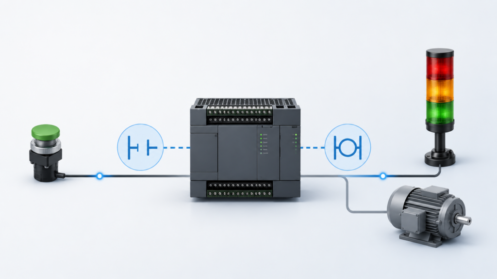
A basic PLC start-stop circuit looks almost impossible to misunderstand.
Press START and the motor runs. Press STOP and the motor stops. A holding contact keeps the command active after the START push button is released.
In simplified form, the logic might be represented as:
Stop_Healthy AND
(Start_Request OR Motor_Run)
→ Motor_Run
Under controlled conditions, this circuit appears stable and predictable.
Real industrial systems are not controlled conditions.
They introduce PLC scan timing, remote I/O delays, contact bounce, asynchronous communication, stale data and uncertain power-recovery states. Once these factors are added, a start-stop circuit that looked obvious on paper can behave very differently on a running machine.
The logic itself may still be correct. The assumptions surrounding it are not.
What the PLC Actually Sees
A PLC does not continuously watch the START and STOP buttons.
During a typical scan, it:
- Reads its inputs.
- Executes the program.
- Calculates output states.
- Updates physical outputs.
- Handles communication and diagnostics.
- Repeats the sequence.
If an input changes immediately after the PLC reads it, the new state may not be processed until the following scan.
For a local push button and a short PLC cycle, that delay may be barely noticeable. If the signal comes through remote I/O, an HMI or another controller, the complete delay can be considerably longer.
The apparent simplicity of the ladder network hides the timing chain behind each contact.
“The Motor Should Stop Instantly”
A normal PLC stop command does not necessarily remove the physical output at the exact moment the field input changes.
The complete path may include:
- The STOP push button opens.
- The input module detects the change.
- Input filtering confirms the new state.
- Remote I/O sends the update, where applicable.
- The PLC receives the input.
- The control task evaluates the stop condition.
- The output process image changes.
- The output module receives the command.
- The contactor or drive reacts.
- The motor mechanically slows down.
Every stage contributes some delay.
For ordinary process control, this may be acceptable. It must not be confused with an emergency-stop function. Safety-related stopping requires an appropriately designed and validated safety system, not an ordinary start-stop bit transmitted through standard PLC communication.
“The HMI Shows the Motor Running”
An HMI does not display every PLC scan.
The PLC may execute every 5 milliseconds while the HMI refreshes a tag every 500 milliseconds. The controller can therefore complete 100 scans between two HMI updates.
During that interval:
- A permissive may disappear.
- The PLC may remove the motor command.
- The drive may stop.
- The permissive may return.
- The HMI may still show the previous green status.
The operator sees RUNNING and assumes the PLC command is still active. In reality, the displayed information may be several hundred milliseconds old.
Motor status should also be represented using separate tags:
Motor_Start_Request
Motor_Output_Command
Contactor_Feedback
Drive_Running
Motor_Speed_Confirmed
A command is not the same as physical confirmation.
“The Latch Is Stable”
A seal-in circuit stores state.
Once the motor command becomes true, it remains true because its own contact replaces the momentary START signal. That stored state makes the circuit useful, but it also creates hidden history.
The current motor command may have been established many scans earlier. Looking at the ladder online does not necessarily reveal exactly what originally activated it.
Latch behaviour becomes less predictable when:
- Automatic and manual logic both control the command.
- Several networks write to the same bit.
- START and STOP occur during the same scan.
- An HMI writes directly to the latched tag.
- The bit is configured as retentive.
- A fault and reset request overlap.
- Communication briefly freezes an input.
A latch should have one clear owner, explicit priorities and a documented power-up state.
Start and Stop Can Overlap
Programmers often assume START and STOP cannot be active together.
In a real installation, they can overlap because:
- An operator presses both buttons.
- An automatic request appears while STOP is active.
- An HMI command arrives during a field-input update.
- A remote stop signal is delayed.
- A communication fault retains the last command.
- Separate PLC tasks update the signals asynchronously.
The program must define the result explicitly.
In most applications, STOP should override START:
IF Stop_Required THEN
    Motor_Run := FALSE;

ELSIF Start_Request AND All_Permissives THEN
    Motor_Run := TRUE;
END_IF;
This is more predictable than relying on the order of separate set and reset instructions.
Duplicate Output Logic
A common source of apparent latch instability is writing to the same output from several locations.
For example:
Network 1:
Manual_Request → Motor_Output

Network 15:
Automatic_Request → Motor_Output

Network 32:
Fault_Active → NOT Motor_Output
Each network may appear reasonable when viewed separately.
However, the PLC executes them in sequence. A later assignment can overwrite an earlier result during the same scan. The first output coil may appear energized online while the physical output remains off because another instruction changed it later.
A stronger design creates intermediate requests:
Manual_Run_Request
Automatic_Run_Request
Maintenance_Run_Request
Stop_Required
Fault_Active
Safety_Healthy
The physical command is then calculated once:
Motor_Output :=
    Safety_Healthy
    AND NOT Fault_Active
    AND NOT Stop_Required
    AND
    (
        Manual_Run_Request
        OR Automatic_Run_Request
        OR Maintenance_Run_Request
    );
The priorities are now visible and independent of accidental output-coil order.
Contact Bounce and Short Input Changes
Mechanical push buttons do not always change state cleanly.
When pressed or released, the contacts may bounce rapidly between open and closed before settling. Input-module filters usually suppress much of this behaviour, but the configured filter time matters.
A heavily filtered input may respond slowly. A filter that is too short may allow several transitions to reach the program.
Possible effects include:
- Multiple start requests
- Repeated counter increments
- Unstable mode selection
- Start and stop overlap
- One-shot instructions triggering several times
Debouncing should be applied deliberately rather than assumed.
The required response time also depends on the signal. A standard control push button can tolerate some filtering. A fast product sensor may require a much faster input or dedicated high-speed hardware.
Remote I/O Changes the Stop Circuit
A stop command connected through remote I/O must pass through the network before reaching the CPU.
The signal path may be:
STOP button
→ Remote input module
→ Input filtering
→ Network update
→ PLC task
→ Output command
→ Network update
→ Remote output
→ Contactor or drive
During healthy operation, the delay may be small and consistent.
During network congestion, a cable fault, device restart or communication timeout, the behaviour can change.
The control system should define what happens if the remote station becomes unavailable:
- Is the motor command removed?
- Does the last output state remain?
- Does the remote module use a configured substitute value?
- Does the PLC generate a specific communication fault?
- Is restart blocked until communication is stable?
These decisions must be configured and tested. They should not be discovered during the first fieldbus failure.
Safety-related stop devices require a safety-rated architecture where demanded by the risk assessment. Standard remote I/O timing should never be casually described as a safe emergency-stop path.
Stale Inputs Can Look Healthy
Communication failure does not always turn every input false immediately.
Depending on the system, the PLC or HMI may temporarily retain the last received state.
A remote permissive could remain true even though the device providing it is no longer communicating.
Instead of using only:
Remote_Readythe program should consider:
Remote_Permissive :=
    Remote_Communication_Healthy
    AND Remote_Data_Valid
    AND Remote_Ready;
A value is useful only when the controller knows it is current.
This is particularly important for signals such as:
- Drive ready
- Valve position
- Pressure available
- Remote system healthy
- Motor feedback
- Guard or access status
A believable stale state can be more misleading than an obvious communication fault.
Restart Behaviour After Power Loss
The behaviour of a simple seal-in circuit after power restoration depends heavily on retentive memory and initialization logic.
If the run latch is non-retentive, it normally returns false when the controller restarts.
If it is retentive, the previous run request may survive.
That stored request can become active again when:
- The PLC returns to RUN.
- Field power is restored.
- Safety conditions recover.
- Remote I/O reconnects.
- The drive becomes ready.
- The output module is re-enabled.
The machine may not start immediately. It may wait silently until the final permissive returns and then start without a fresh operator command.
A safer design generally separates the retained operating settings from the actual run request. After power recovery, the program should enter a defined initialization state and require an intentional restart where appropriate.
The precise requirements depend on the machine and its risk assessment, but automatic restart must never be an accidental side effect of retaining a latch.
Startup Sequencing Problems
A motor circuit may depend on several startup conditions:
- Safety circuit healthy
- Overload reset
- Remote I/O connected
- Drive communication available
- Drive ready
- Valve open
- Process pressure healthy
- Automatic mode selected
These conditions rarely become valid simultaneously.
If the program evaluates the start request only once, a short HMI pulse may disappear before the final permissive becomes healthy.
The operator presses START while the drive appears ready. The PLC sees the start request during one scan and the drive-ready signal during a later scan. The two conditions never overlap, so the motor does not start.
Possible solutions include:
- Holding the start request until it is accepted
- Requiring readiness before enabling the start control
- Using a command-and-acknowledgement handshake
- Displaying the exact missing permissive
- Applying a controlled startup validation period
The correct solution depends on the process. Randomly adding timers may hide the symptom without fixing the state design.
Bypass Conditions Create False Health
A maintenance bypass may be represented as:
Valve_OK := Valve_Open_Feedback OR Valve_Bypass;This permits operation when the real feedback is missing.
The problem is that every part of the program now sees Valve_OK as healthy. The distinction between real confirmation and bypassed operation disappears.
A better design preserves both states:
Valve_Feedback_Healthy := Valve_Open_Feedback;

Valve_Start_Permitted :=
    Valve_Open_Feedback
    OR
    (
        Valve_Bypass
        AND Maintenance_Mode
        AND Bypass_Authorized
    );
The HMI should continue showing that the real feedback is absent.
Active bypasses should be:
- Clearly visible
- Access controlled
- Alarmed or logged
- Limited to an approved operating mode
- Reviewed before automatic operation
- Removed after maintenance
A bypass should permit controlled abnormal operation. It should not make the PLC believe the field condition is genuinely healthy.
A Better Start-Stop Structure
A predictable motor-control function separates the different states.
Requests
- Physical START button
- HMI start request
- Automatic sequence request
- Manual run request
Stop conditions
- Physical STOP button
- HMI stop request
- Process stop
- Fault stop
- Mode-change stop
Permissives
- Communication valid
- Device ready
- Process conditions healthy
- Required positions confirmed
Command
One internal command is calculated using explicit priorities.
Physical output
The output address is assigned in one location.
Feedback
The program verifies that the contactor, drive or motor actually responded.
This structure is longer than a single seal-in rung, but it is considerably easier to test and diagnose.
Testing the “Simple” Circuit Properly
Commissioning should include more than pressing START and STOP once.
Test:
- START and STOP simultaneously
- START while a permissive is missing
- Permissive loss while running
- Power failure while the motor is commanded
- PLC restart with retained data
- Remote I/O disconnection
- Communication recovery
- Rapid repeated button presses
- Automatic-to-manual mode change
- Reset while a fault remains active
- Bypass activation and removal
- HMI communication interruption
- Output feedback failure
For every test, confirm:
- Final command state
- Physical output state
- Machine response
- Alarm behaviour
- Restart requirements
- HMI indication
- Recovery path
A circuit is predictable only after abnormal combinations have also been tested.
Final Thoughts
Simple PLC logic is often only simple on the screen.
Behind each ladder contact may be a sensor response, input filter, network update, process-image transfer, PLC task and HMI polling cycle. A holding contact may preserve an old command. A permissive may contain stale data. A bypass may hide an unhealthy field condition.
That is the illusion of simple logic.
The ladder network looks obvious, but its real behaviour depends on timing, communication and stored state.
Reliable start-stop programming requires clear ownership, explicit priorities, validated data and defined restart behaviour.
The circuit should not merely work when every signal arrives in the expected order.
It should remain predictable when they do not.