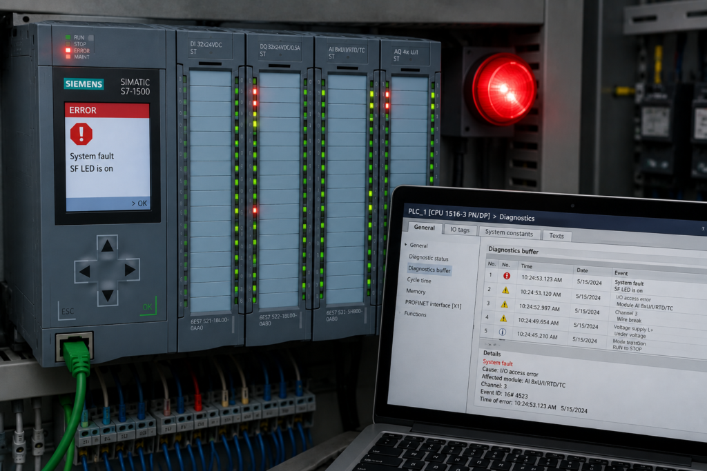
Permissives are conditions that must be satisfied before a PLC allows equipment to operate.
A motor may require healthy pressure, an available drive and a correctly positioned valve. A conveyor might need confirmation that the downstream machine is ready. A fan may require airflow, guards and dampers to be in their expected states.
The basic concept appears simple:
Start request
      ↓
Are all permissives healthy?
      ↓
     Yes
      ↓
Enable the output
The difficulty is that industrial permissives rarely update simultaneously or remain perfectly stable.
One condition may come from local I/O, another from a remote PROFINET station and a third from a VFD communication telegram. Analog conditions may be filtered. HMI indications may refresh several hundred milliseconds after the PLC has already processed a change.
This creates failures that look like bad logic even when the Boolean expression is technically correct.
Common PLC Permissives
Typical operating permissives include:
- Safety system healthy
- Guard or access door closed
- Motor overload healthy
- VFD ready
- Air pressure available
- Cooling airflow confirmed
- Lubrication pressure established
- Valve in the required position
- Upstream or downstream equipment ready
- Communication with remote equipment healthy
- Temperature, pressure or level inside an acceptable range
Not every condition should be treated identically.
Some conditions are required only before starting. Others must remain healthy throughout operation. Some should stop the machine immediately, while others may permit a controlled shutdown.
That distinction must be designed deliberately.
Startup Permissives Versus Running Interlocks
A common mistake is using the same combined Boolean bit for both startup and operation.
For example:
Motor_Permissive :=
    Drive_Ready
    AND Pressure_Healthy
    AND Valve_Open
    AND Downstream_Ready;
The motor starts when Motor_Permissive is true and stops whenever it becomes false.
This may be acceptable in a simple process, but it can create nuisance shutdowns when one condition briefly changes during normal operation.
A stronger design separates the two decisions:
Start_Permissive :=
    Drive_Ready
    AND Communication_Valid
    AND Pressure_Stable
    AND Valve_Open_Confirmed;

Run_Permissive :=
    Drive_Healthy
    AND Critical_Pressure_Healthy
    AND No_Process_Trip;
The startup permissive may require every device to be fully initialized and stable. Once running, the system may use a different set of conditions and defined delay times.
Safety-related conditions must still be handled through the required safety-rated system rather than ordinary standard PLC logic.
Delayed Permissive Updates
Imagine that a motor requires three conditions:
- Local overload contact healthy
- Remote pressure switch healthy
- Drive ready through PROFINET
The operator presses START.
During the first scan, the PLC sees:
Start_Request = TRUE
Overload_Healthy = TRUE
Pressure_Healthy = TRUE
Drive_Ready = FALSE
The drive-ready telegram updates one scan later:
Start_Request = FALSE
Drive_Ready = TRUE
Every condition appeared healthy to the operator, but the short start request never overlapped with all the permissives inside the PLC task.
The machine refuses to start intermittently.
Possible solutions include:
- Enable the start button only after all readiness conditions are valid.
- Capture the start request until it is accepted or cancelled.
- Use a request-and-acknowledgement sequence.
- Require a fresh start after a defined timeout.
- Display the exact permissive that blocked the request.
A stored start request must not remain active indefinitely. Otherwise, the equipment could begin running much later when a missing condition unexpectedly returns.
Asynchronous Remote I/O
Remote I/O introduces communication time between the field device and the PLC.
A typical signal path is:
- Field condition changes.
- Input module detects the new state.
- Module filtering confirms the signal.
- Remote station prepares the next data update.
- Network sends the data.
- CPU receives the updated process image.
- PLC task evaluates the permissive.
Related signals can therefore arrive during different scans.
Suppose two valve-position switches change physically at nearly the same time. One is local and the other is connected through remote I/O.
For one scan, the PLC might see:
Valve_A_Open = TRUE
Valve_B_Open = FALSE
The permissive drops even though both valves reached their positions correctly.
If this temporary mismatch stops the process immediately, the machine may develop intermittent sequence failures.
Use state validation when the process allows it:
Both_Valves_Confirmed :=
    Valve_A_Open
    AND Valve_B_Open;

Both_Valves_Stable :=
    Both_Valves_Confirmed continuously true
    for the validation period;
The validation time should reflect real communication and mechanical timing. It should not be used to conceal unreliable devices or unsafe conditions.
Noisy Permissives
Pressure switches, flow switches and mechanical contacts may change state repeatedly near their switching points.
A motor might start, lower the process pressure slightly and cause its own permissive to drop. When the motor stops, pressure recovers and the permissive returns. The start command then becomes valid again.
The system can oscillate:
- Pressure becomes healthy.
- Motor starts.
- Pressure briefly falls.
- Motor stops.
- Pressure recovers.
- Motor restarts.
Possible causes include:
- Insufficient hysteresis
- Contact bounce
- Electrical noise
- Poor sensor placement
- Incorrect pressure limits
- Process instability
- Excessive analog sensitivity
A digital permissive may need debounce timing. An analog permissive often benefits from separate on and off thresholds.
For example:
Pressure_Healthy becomes TRUE above 3.2 bar.
Pressure_Healthy becomes FALSE below 2.8 bar.
The difference between the two limits prevents the status from rapidly switching around one threshold.
Analog Permissives and Filtering
Analog conditions often create hidden delays.
Suppose low pressure should stop a pump. The raw process pressure drops quickly, but the signal passes through:
- Transmitter damping
- Analog module filtering
- PLC averaging
- HMI smoothing
The HMI still displays acceptable pressure while the physical process is already below the required level.
If the shutdown logic uses the same heavily filtered value, the response will be delayed.
Consider using separate signal paths:
- Raw or lightly filtered signal for fast protection
- Moderately filtered signal for control
- More heavily filtered signal for operator display
Filtering should be selected according to the function. A value intended for a smooth HMI trend may be unsuitable for a time-critical interlock.
Stale Permissive Data
One of the most dangerous conditions is a permissive that remains true after communication has failed.
For example:
Remote_Airflow_OK = TRUEThe remote device disconnects, but the last value remains stored. The PLC continues seeing a healthy airflow condition.
A reliable remote permissive should include validity information:
Airflow_Permissive :=
    Remote_Communication_Healthy
    AND Remote_Data_Valid
    AND Remote_Airflow_OK;
Important communication values may also require:
- Heartbeat monitoring
- Update counters
- Timestamps
- Device status words
- Signal-age monitoring
- Plausibility checks
A value should not be considered healthy simply because its number or Boolean state still looks reasonable.
The HMI Can Show the Wrong Moment
An HMI does not normally refresh at the same speed as the PLC.
The PLC may scan every 5 milliseconds while the HMI updates every 500 milliseconds. During that time, the controller can process approximately 100 program cycles.
A permissive may drop for 20 milliseconds, stop the equipment and recover before the HMI polls again.
The operator sees every permissive displayed in green and concludes that the motor stopped without a reason.
For intermittent permissive failures, capture:
- Raw condition
- Processed condition
- Communication validity
- Combined permissive
- Output command
- Sequence step
- First failed condition
- Timestamp
A PLC trace or first-out fault recorder provides much more useful evidence than a slowly refreshing HMI screen.
First-Out Permissive Diagnostics
When one condition stops a machine, several secondary conditions may fail afterward.
For example:
- Cooling airflow disappears.
- Motor stops.
- Process pressure falls.
- Downstream-ready signal disappears.
- Sequence timer expires.
By the time maintenance arrives, four alarms are active.
Only the airflow failure explains the original event.
A first-out diagnostic system should record:
- First permissive that failed
- Date and time
- Current sequence step
- Operating mode
- Output command state
- Relevant process values
- Communication quality
The record should remain available even after the permissive recovers.
Missing Validation During Recovery
Permissives may return in an unstable order after a fault or communication interruption.
For example:
- Network connection returns.
- Device-connected bit becomes true.
- Old process data is briefly visible.
- Device finishes initialization.
- Fresh data begins updating.
- Ready status finally becomes valid.
If the PLC accepts the first connected indication as a healthy permissive, it may restart equipment before the device is actually ready.
Recovery logic should distinguish between:
- Connected
- Communicating
- Data valid
- Device ready
- Process condition healthy
A restart permissive may require all necessary conditions to remain continuously valid for a defined period before the reset or start is accepted.
Hidden Bypass Hazards
Bypasses are frequently added to permissive logic during commissioning.
A typical expression might be:
Valve_OK :=
    Valve_Open_Feedback
    OR Valve_Bypass;
When the bypass is active, the rest of the program sees Valve_OK as healthy even though the physical valve feedback is absent.
This hides the real equipment condition.
A better structure preserves the distinction:
Valve_Feedback_Healthy :=
    Valve_Open_Feedback;

Valve_Operation_Permitted :=
    Valve_Open_Feedback
    OR
    (
        Valve_Bypass
        AND Maintenance_Mode
        AND Bypass_Authorized
    );
The HMI should continue to show that the real feedback is missing.
Active bypasses should be:
- Clearly indicated
- Access controlled
- Alarmed or logged
- Limited to approved operating modes
- Removed after maintenance
- Considered during power recovery
- Prevented from silently enabling unsafe automatic operation
A bypass permits abnormal operation. It does not make the underlying field condition healthy.
Duplicate Permissive Logic
Another common problem occurs when different program sections calculate the same permissive differently.
For example:
Motor_Ready in one block:
Drive_Ready AND Pressure_OK

Motor_Ready in another block:
Drive_Ready AND Valve_Open
Depending on which assignment executes last, one set of conditions is ignored.
Permissives should have one authoritative calculation point.
Individual conditions can be organized clearly:
Perm_Safety
Perm_Drive
Perm_Pressure
Perm_Valve
Perm_Communication
Perm_Process
Then combined once:
Motor_Start_Permissive :=
    Perm_Safety
    AND Perm_Drive
    AND Perm_Pressure
    AND Perm_Valve
    AND Perm_Communication
    AND Perm_Process;
This structure also makes HMI diagnostics easier because each missing condition can be displayed individually.
Avoid One Generic “System Ready” Bit
A single System_Ready bit is convenient for normal operation but poor for troubleshooting.
When it becomes false, the technician still needs to know why.
Keep detailed conditions available:
- Safety not ready
- Drive communication missing
- Pressure unstable
- Valve position invalid
- Remote data stale
- Upstream machine unavailable
- Automatic mode not selected
A diagnostic screen should show both:
System_Ready = FALSEand:
Blocked by: Valve V12 not confirmed openClear diagnostic reasons reduce commissioning time and discourage technicians from bypassing conditions merely to discover which one is causing the problem.
Designing Reliable Permissive Logic
A robust permissive structure should include several layers.
Raw field state
The unprocessed input or communication value.
Data validity
Confirmation that the source is connected, current and trustworthy.
Condition processing
Debouncing, hysteresis, scaling or plausibility checks.
Startup permissive
Conditions required before operation begins.
Running interlock
Conditions that must remain healthy during operation.
Recovery validation
Conditions required before reset or restart.
Diagnostic reason
Information explaining which condition blocked or stopped operation.
This may require more tags than a single Boolean expression, but it makes the behaviour predictable and maintainable.
Recommended Troubleshooting Workflow
When startup fails randomly or an output drops unexpectedly, avoid changing the ladder structure immediately.
First:
- Identify every required permissive.
- Record the raw field states.
- Check communication and data-valid signals.
- Compare local and remote update timing.
- Review analog filtering and debounce settings.
- Capture the first condition that changes.
- Check whether the HMI is displaying stale information.
- Verify whether multiple blocks write to the same permissive.
- Test recovery after communication or power loss.
- Confirm that bypasses are inactive and clearly indicated.
A logic modification should follow evidence, not replace it.
Tests Every Permissive System Should Pass
Commissioning should include:
- Start with one permissive missing
- Permissive arriving late
- Brief noisy permissive transition
- Remote I/O disconnection
- Communication recovery
- Analog value crossing its threshold slowly
- Analog value changing rapidly
- Reset while a permissive remains unhealthy
- Power restoration with stale data
- Bypass activation and removal
- Multiple permissives changing together
- Permissive loss while equipment is running
For every test, verify:
- Whether startup is blocked correctly
- Whether the output stops as intended
- Whether the first failed condition is recorded
- Whether restart requires deliberate action
- Whether the HMI displays the real cause
- Whether stale data is rejected
- Whether the recovery sequence is stable
Final Thoughts
Permissive logic is not merely a group of contacts placed in series.
Each condition has its own timing, source, quality and expected behaviour. Some signals are local, others remote. Some are noisy, filtered or delayed. Some may remain at their last value after communication fails.
Reliable permissive handling requires more than checking whether every bit is currently true.
The PLC must also know:
- Whether the data is valid
- How long the condition has been stable
- Whether it is required only for startup or throughout operation
- What happens when it disappears
- How it is restored after a fault
- Whether a bypass is active
- Which condition failed first
Before rewriting logic, verify the raw conditions and their timing.
The permissive expression may be correct.
The data feeding it may not be.