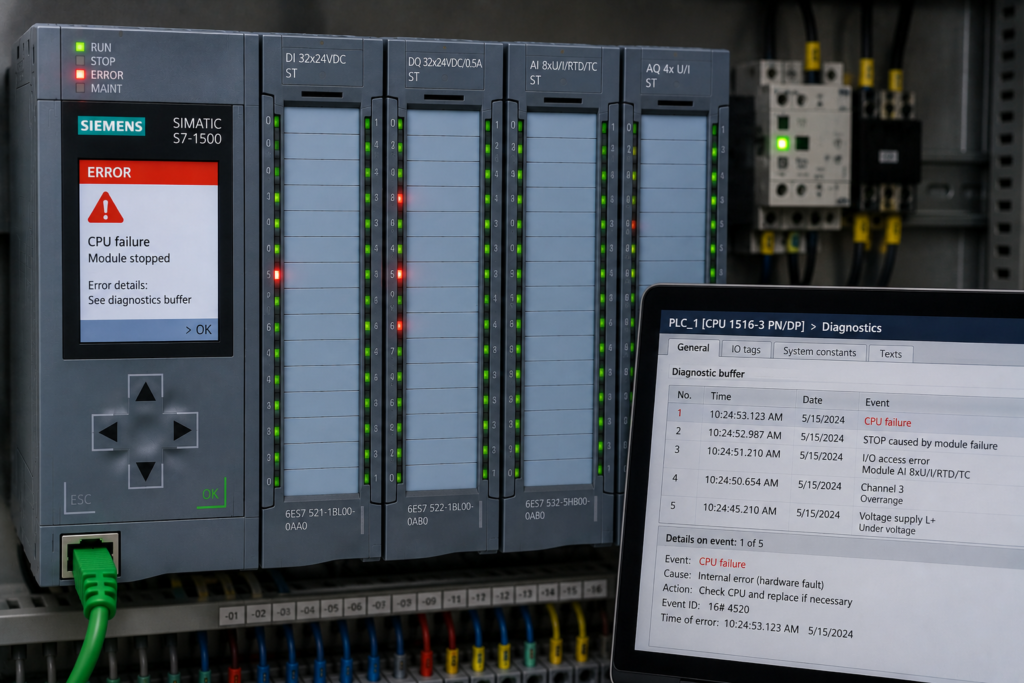
Industrial PLC systems rarely fail at convenient times.
The line does not usually stop while the complete engineering team is standing beside the machine with drawings, backups and plenty of time to investigate.
Failures happen during production:
- At startup
- After maintenance
- During shift change
- Following an online edit
- After a power interruption
- During unstable commissioning
- In the middle of a high-priority production order
At 03:00 AM, the technical problem is only part of the challenge.
Operators want production restored. Management wants an estimated restart time. Maintenance personnel may already be changing field devices, and several people may be discussing different theories at once.
Under that pressure, disciplined troubleshooting can quickly turn into uncontrolled experimentation.
Bits are forced. Timers are extended. Interlocks are bypassed. Multiple online edits are applied without recording the original values.
The machine may eventually run again—but nobody knows which change actually restored it or whether the recovery introduced a new hazard.
Why Recovery Pressure Creates Additional Failures
A stopped machine creates urgency.
Urgency encourages technicians to focus on one immediate objective:
Make the machine run.
That objective is understandable, but it is incomplete.
A successful recovery must also ensure that the machine:
- Starts intentionally
- Operates predictably
- Retains required protective functions
- Can stop correctly
- Can recover again after the next fault
- Does not contain undocumented temporary changes
Many serious commissioning problems are not caused by one major programming error.
They develop through several smaller actions:
Original fault
↓
Input forced
↓
Interlock bypassed
↓
Timer increased
↓
Online edit added
↓
Sequence manually advanced
↓
Machine starts
The final operating condition may depend on every temporary action remaining in place.
Production has been restored, but the control system is now less understood and potentially less safe than before the failure.
The First Rule: Stop Adding Changes
When troubleshooting becomes unstable, the first professional action is often to stop changing the system.
This does not mean abandoning recovery. It means creating a controlled baseline.
Before making another edit:
- Identify everyone currently working on the machine.
- Stop simultaneous program changes.
- Record active PLC forces.
- Record active HMI bypasses.
- Identify recent online edits.
- Save the current PLC state and diagnostic information.
- Confirm the machine’s physical condition.
- Assign one person to coordinate changes.
Without this pause, several people may unknowingly work against one another.
One engineer may force an input true while another rewrites the logic because the input appears healthy. Maintenance may repair the sensor while the force remains active, preventing anyone from observing the real signal.
Safety Comes Before Production Recovery
Before troubleshooting control logic, determine whether personnel can safely work around the equipment.
Questions include:
- Is stored mechanical or pneumatic energy present?
- Could a retained command cause unexpected movement?
- Are guards, safety circuits and emergency stops functional?
- Is manual intervention inside the machine required?
- Does electrical or mechanical isolation need to be applied?
- Are temporary safety measures required for testing?
Where exposure to hazardous energy exists, follow the site’s approved isolation and lockout/tagout procedures.
Ordinary PLC commands, HMI stop buttons and software forces are not energy-isolation devices.
A machine that appears stopped in software may still contain electrical, pneumatic, hydraulic, thermal or gravitational energy.
Establish a Recovery Leader
Live plant recovery becomes chaotic when several people make independent decisions.
A recovery leader should coordinate:
- Safety status
- Current machine condition
- PLC changes
- Field work
- Operator actions
- Communication with production
- Rollback decisions
This person does not need to perform every technical task. The role is to maintain one shared recovery plan.
A simple change log should include:
Time
Person
Observed condition
Action taken
Expected result
Actual result
Rollback method
For example:
03:12 — Drive 2 ready missing after network recovery
03:16 — Confirmed drive online but status data stale
03:20 — Cleared communication session and restarted device
03:24 — Fresh status data restored
03:27 — No PLC code change required
This prevents repeated work and preserves evidence for the later root-cause review.
Capture the System Before Resetting It
Repeatedly pressing RESET often destroys valuable information.
Before resetting the fault, record:
- Current machine state
- Previous sequence state
- First-out fault
- All active faults
- Start and stop requests
- Output commands
- Physical feedback
- Safety status
- Network health
- Important analog values
- PLC cycle time
- Recent diagnostic-buffer events
- Active forces and bypasses
The first failed condition may disappear as soon as the machine stops.
For example:
- Drive communication fails.
- Motor stops.
- Flow disappears.
- Pressure falls.
- Several process alarms activate.
After reset, the drive reconnects and every current condition appears healthy.
Without a first-out record or diagnostic capture, the original communication failure may be missed.
Verify the Physical Machine State
The PLC state and the physical machine state may no longer agree.
After a trip or power interruption:
- A pneumatic valve may return to its fail position.
- A cylinder may drift.
- A motor contactor may remain mechanically stuck.
- A drive may lose position reference.
- Product may remain between sensors.
- Tank level may continue changing.
- Operators may move components manually.
Do not assume that the sequence can resume from its retained step.
Compare:
PLC expected state
versus
actual field condition
A sequence that remembers CONVEYING_PRODUCT is not enough. Confirm that the conveyor, product position, downstream availability and associated sensors match that state.
When the physical condition cannot be verified, enter a controlled recovery state rather than forcing the sequence forward.
Use a Deterministic Troubleshooting Order
A disciplined troubleshooting sequence reduces random changes.
1. Confirm the reported symptom
Determine exactly what failed.
Was it:
- No startup
- Unexpected stop
- Output command missing
- Output commanded but no field response
- Sequence stuck
- Communication failure
- Analog value invalid
- Safety system not reset
Avoid broad descriptions such as “the PLC is broken.”
2. Identify the current state
Determine:
- Current sequence state
- Expected transition
- Conditions blocking that transition
- Required outputs
- Actual feedback
3. Check raw field conditions
Inspect the original input states before filtered, bypassed or combined permissive tags.
4. Verify signal quality
For network and analog signals, confirm:
- Communication healthy
- Data updating
- Module diagnostics normal
- Value valid
- Signal not stale
5. Check output ownership
Confirm that only one program section owns the final command.
6. Review recent changes
Look for:
- Online edits
- Timer changes
- New bypasses
- Device replacements
- Network configuration changes
- Electrical maintenance
7. Reproduce one condition at a time
Change only one controlled variable and record the result.
This method may initially feel slower than forcing several bits simultaneously. In practice, it usually reaches the root cause faster.
The Discipline of PLC Forces
PLC forces can be valuable diagnostic tools.
They can also create some of the most confusing and dangerous commissioning conditions.
A force replaces the normal relationship between the PLC program and a tag or I/O channel. The online logic may show one result while the forced value controls the effective behaviour.
Common risks include:
- Forgetting that a force remains active
- Forcing an input that hides a repaired sensor
- Forcing an output without its normal interlocks
- Leaving forces active after disconnecting
- Another engineer not knowing a force exists
- Forces surviving longer than expected
Before applying a force, document:
- Exact tag or channel
- Reason for the force
- Expected machine response
- Possible hazardous movement
- Person responsible
- Removal condition
Forces should be limited to controlled tests and removed immediately afterward.
Before production restart, review the controller’s complete force table—not only the tag currently being monitored.
Never Force Safety Functions Through Standard PLC Logic
Safety-related inputs and outputs require the approved safety architecture.
Do not use ordinary PLC forces or bypass logic to defeat:
- Emergency-stop functions
- Guard interlocks
- Safe motion functions
- Safety contactor feedback
- Required protective devices
Testing safety systems requires appropriate procedures, authorization and validated equipment.
Standard PLC logic must not be used as a substitute for required safety-rated control.
Bypasses Must Remain Visible
A maintenance bypass should never make the HMI display an unhealthy device as healthy.
Weak logic may use:
Valve_OK :=
    Valve_Open_Feedback
    OR Valve_Bypass;
When the bypass is active, Valve_OK appears healthy everywhere.
A stronger structure keeps the states separate:
Valve_Feedback_Healthy :=
    Valve_Open_Feedback;

Valve_Operation_Permitted :=
    Valve_Open_Feedback
    OR
    (
        Valve_Bypass
        AND Maintenance_Mode
        AND Bypass_Authorized
    );
The HMI should continue showing:
Valve feedback missing
Bypass active
Operation temporarily permitted
Bypasses should be authorized, logged and reviewed before normal operation resumes.
Online Edit Safety
Online editing is powerful because it allows changes without stopping the controller.
That same capability makes it dangerous under pressure.
An online edit can:
- Change sequence priority
- Alter output ownership
- Reset or preserve internal states unexpectedly
- Change timer behaviour
- Modify data structures
- Affect multiple machines using the same function block
- Create differences between the online PLC and offline project
Before editing, answer:
- What exact fault is the change intended to correct?
- Which states can execute the modified logic?
- Which outputs can be affected?
- Is the current machine state compatible with the edit?
- What happens if the edit fails?
- How will the original logic be restored?
Do not edit merely because a suspicious rung is visible.
Collect evidence first.
One Controlled Change at a Time
Several simultaneous changes make cause and effect impossible to establish.
Avoid this pattern:
Increase timer
Force input
Disable alarm
Change latch reset
Restart drive
If the machine starts, nobody knows which action mattered.
Use:
One hypothesis
↓
One controlled change
↓
Observe result
↓
Record evidence
↓
Keep or roll back
When a change does not produce the expected result, restore the original configuration before testing the next theory.
Timer Changes Require Physical Justification
Increasing a timer is one of the most common emergency modifications.
Sometimes the device genuinely needs more time. More often, the timer is changed without identifying why the response became slower.
A valve timeout may occur because:
- Air pressure is low
- The valve is mechanically sticking
- Feedback arrives through delayed remote I/O
- The sensor is misaligned
- Communication data is stale
- The original timer is genuinely too short
Changing five seconds to fifteen seconds may allow startup, but it can also delay recognition of a real mechanical failure.
Before extending a timer, record the actual response time over several cycles and verify the field condition.
Preserve the Original Program
Before significant online work, create a recoverable baseline.
Depending on the platform and site procedure, this may include:
- Uploading the current running project
- Saving the latest offline project
- Recording PLC firmware and hardware configuration
- Exporting critical data blocks or recipes
- Saving drive and HMI parameters
- Recording online differences
- Creating a timestamped backup
The backup must represent the actual running system.
An old laptop copy is not automatically a valid rollback point.
Define the Rollback Before the Edit
Rollback planning should happen before a change is applied.
A rollback plan should answer:
- Which file or program version will be restored?
- Which data values must be preserved?
- Will the controller require a stop or restart?
- What machine state is required?
- How will drives and remote devices react?
- Who authorizes the rollback?
- How will the restored system be tested?
Without a rollback plan, engineers may continue adding fixes because returning to the previous condition feels too risky.
Startup Recovery After Changes
After forces, edits or device repairs, do not jump directly back into automatic production.
Use a controlled startup sequence:
Confirm all forces removed
↓
Confirm bypass status
↓
Validate program version
↓
Check safety system
↓
Validate I/O and communications
↓
Confirm analog data quality
↓
Verify actuator positions
↓
Run manual or low-risk functional tests
↓
Enter READY
↓
Issue fresh START command
The machine should not resume merely because the last fault disappeared.
Verify Inputs Before Outputs
When the machine fails to move, technicians often focus immediately on the output coil.
A better path is:
Request
↓
Permission
↓
Command
↓
Physical output
↓
Feedback
For a motor:
Automatic_Run_Request
Motor_Start_Permissive
Motor_Output_Command
Contactor_Output
Contactor_Feedback
Drive_Running_Status
This reveals whether the problem lies in:
- Sequence request
- Interlock logic
- Output ownership
- Electrical output
- Contactor or drive
- Feedback circuit
Forcing the output skips most of this diagnostic path.
Do Not Trust the HMI Alone
The HMI may display delayed, filtered or stale information.
During recovery, inspect:
- Raw PLC inputs
- Processed permissives
- Communication-valid bits
- State variables
- Output commands
- Physical feedback
A green HMI indicator does not prove that the PLC saw the condition during the failed scan.
For intermittent faults, use trace data or first-out diagnostics.
Create a Recovery State Instead of Forcing Steps
When a sequence is stuck, forcing the next step number may move the machine into a state whose prerequisites were never satisfied.
For example, forcing:
Machine_State := RUNNINGmay assume that:
- Valves are positioned
- Drives are ready
- Product is correctly located
- Pressure is established
- Communication data is valid
A dedicated recovery state is safer:
RECOVERY_REQUIREDIt can:
- Block automatic outputs
- Validate positions
- Permit limited manual movement
- Re-establish communications
- Confirm fresh process data
- Return the machine to READY
Recovery should restore known conditions—not skip unknown ones.
Separate Temporary Recovery From Permanent Repair
A temporary recovery action may be necessary to finish a batch or move equipment into a maintainable position.
That action should be identified clearly as temporary.
Record:
- What was bypassed
- Why it was necessary
- Operating restrictions
- Person authorizing it
- Required permanent repair
- Expiration or removal time
Do not allow a temporary recovery method to become the accepted production procedure.
Use Stop Conditions During Recovery
A recovery test should have clear stop criteria.
Stop the test immediately when:
- Unexpected movement occurs
- A different output energizes
- Safety status changes
- Communication becomes invalid
- A new fault appears
- The physical process does not match the PLC state
- The result differs from the expected response
Without predefined stop criteria, teams may continue testing despite accumulating evidence that their assumption is wrong.
Communicate Machine Status Clearly
Operators and management need accurate information during recovery.
Avoid overconfident statements such as:
It is definitely the PLC.
Use specific observations:
The PLC is requesting the motor, but the drive does not report ready.
Or:
The machine is blocked because remote valve feedback is stale after communication recovery.
Clear descriptions reduce pressure for random programming changes and help coordinate electrical, mechanical and process teams.
A Practical 03:00 AM Recovery Procedure
A controlled recovery can follow this sequence.
Phase 1: Stabilize
- Stop uncontrolled changes.
- Establish safe working conditions.
- Assign a recovery leader.
- Identify every active force and bypass.
Phase 2: Capture
- Record machine state.
- Save first-out faults.
- Save diagnostic buffers.
- Record relevant raw signals.
- Preserve the current program version.
Phase 3: Diagnose
- Confirm the physical condition.
- Trace request, permission, command and feedback.
- Verify communication and data quality.
- Review recent maintenance and edits.
Phase 4: Test
- Form one hypothesis.
- Make one controlled change.
- Observe and record the result.
- Roll back unsuccessful changes.
Phase 5: Recover
- Remove forces.
- Review bypasses.
- Validate startup permissives.
- Enter a controlled recovery or startup state.
- Require a deliberate start command.
Phase 6: Verify
- Test normal startup.
- Test normal stop.
- Confirm fault and reset behaviour.
- Check alarms and HMI indications.
- Verify that backups match the running system.
Phase 7: Handover
- Record temporary conditions.
- Assign permanent corrective actions.
- Communicate operating restrictions.
- Schedule a formal root-cause review.
Post-Recovery Verification
A machine running again is not proof that recovery is complete.
Verify:
- No unintended forces remain
- No undocumented bypasses remain
- Online and offline projects match
- Normal startup works repeatedly
- Normal shutdown works
- Fault reset does not cause automatic restart
- Output feedback is correct
- Alarms identify the real fault
- Communication recovery is stable
- Power-recovery behaviour remains safe
The machine should be tested under the condition that originally caused the failure where safely practical.
Perform a Root-Cause Review
Emergency recovery restores production.
It does not replace root-cause analysis.
The follow-up review should identify:
- Original initiating fault
- Why existing diagnostics were insufficient
- Every force, bypass and edit used
- Which action restored operation
- Whether any temporary logic remains
- Whether startup or recovery architecture needs redesign
- Whether documentation and training need improvement
Repeated 03:00 AM failures usually indicate a structural problem, not bad luck.
Build Recovery Features Before the Failure
The best emergency recovery tools are designed before the emergency.
Useful features include:
- Current and previous state display
- First-out fault recorder
- Transition history
- Raw and processed permissive views
- Active bypass register
- Force and maintenance checklists
- Signal-quality diagnostics
- Output command and feedback comparison
- Startup and recovery state machines
- Version-controlled backups
A system with clear diagnostics reduces the temptation to force and bypass blindly.
Final Thoughts
Live plant pressure changes how people troubleshoot.
Urgency encourages rapid edits, hidden bypasses and several simultaneous actions. These may restore production temporarily while making the control system more difficult to understand and less predictable.
Professional recovery requires discipline:
- Stabilize the situation
- Capture evidence
- Verify the physical machine
- Control forces and bypasses
- Make one change at a time
- Prepare rollback before editing
- Recover through a defined startup path
- Verify the complete machine afterward
The objective is not only to get the line running.
It is to restore operation without creating the next failure.
At 03:00 AM, the strongest engineer is rarely the person who changes the most logic.
It is the person who keeps the recovery controlled while everyone else feels pressure to rush.