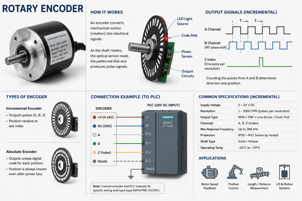
An encoder that works perfectly at low speed but loses position, counts incorrectly or becomes unstable at high speed usually does not have a mysterious software problem.
The fault often appears because the encoder system has crossed a physical or electrical limit.
At low speed, the PLC has plenty of time to recognize every pulse. As speed increases, the pulses become shorter and arrive more frequently. Eventually, the input circuit, wiring, encoder output or PLC program can no longer capture them reliably.
The result may look like:
- Incorrect position
- Lower-than-expected speed
- Gradual counting error
- Random direction changes
- Missed index pulses
- Motion stopping at inconsistent positions
- A machine that works during jogging but fails in automatic mode
The most important question is not simply whether the encoder produces pulses.
It is whether the complete signal chain can process those pulses at the maximum operating speed.
Why Speed Changes Everything
A rotary encoder produces a certain number of pulses for every shaft revolution.
As shaft speed increases, pulse frequency also increases.
The basic relationship is:
Encoder frequency =
Pulses per revolution × Revolutions per minute ÷ 60
Suppose an encoder produces 1,024 pulses per revolution and rotates at 3,000 rpm:
1,024 × 3,000 ÷ 60 = 51,200 pulses per secondThe encoder is producing a 51.2 kHz signal.
For a quadrature encoder, the effective counting rate may be higher if the counter evaluates every rising and falling edge on both A and B channels.
With ×4 quadrature counting:
51,200 × 4 = 204,800 counts per secondThe PLC input and high-speed counter must therefore process approximately 204.8 kHz.
An encoder that appears slow mechanically can create a very fast electrical signal.
The Most Common Cause: Using a Normal PLC Input
Standard PLC digital inputs are usually intended for pushbuttons, limit switches, relays and ordinary sensors.
They may include input filtering to reject contact bounce and electrical noise.
That filtering becomes a problem when the input is connected to a fast encoder.
For example, a normal input may have a filter time of several milliseconds. An encoder pulse at high speed may remain active for only a few microseconds.
The PLC never sees it.
At low speed, the pulse remains active long enough to pass through the filter. At high speed, many pulses disappear before reaching the program.
Encoders should normally be connected to:
- Dedicated high-speed counter inputs
- High-speed digital input modules
- Motion-control modules
- Drive encoder inputs
- Dedicated encoder interface cards
Do not assume that every 24 V digital input can count encoder pulses.
PLC Scan Time Is Too Slow
A standard PLC program typically reads the input process image once per scan.
Suppose the PLC scan time is 10 milliseconds.
During one scan, a 20 kHz encoder signal produces:
20,000 × 0.01 = 200 pulsesIf the program uses an ordinary contact and counter instruction, it may observe only the signal state at the moment the input image is updated.
Hundreds of transitions can occur between scans without being detected.
A high-speed counter solves this by counting pulses in hardware independently of the normal PLC scan.
The program then reads the accumulated count rather than attempting to detect every pulse itself.
This distinction is critical:
Normal PLC logic:
Samples the input periodically

High-speed counter:
Counts hardware edges continuously
A faster program scan may improve some applications, but it is not a reliable replacement for a proper hardware counter.
High-Speed Counter Frequency Limit
Dedicated high-speed counters also have limits.
A PLC may support different maximum frequencies depending on:
- Input channel
- Voltage level
- Wiring mode
- Single-phase or quadrature operation
- Number of active channels
- Filter configuration
- Input type
- Counting mode
For example, a high-speed counter may support:
- 100 kHz in single-channel mode
- 50 kHz in A/B quadrature mode
- Lower frequency when additional filtering is enabled
The exact figures depend on the PLC or counter module.
Compare the calculated maximum encoder frequency with the documented input limit.
Do not compare only the encoder’s pulse frequency. Include the quadrature evaluation factor where applicable.
Pulses per Revolution May Be Misunderstood
Encoder specifications can use several related terms:
- Pulses per revolution
- Cycles per revolution
- Lines per revolution
- Counts per revolution
- Edges per revolution
- Resolution
These terms are not always used consistently.
A quadrature encoder rated at 1,000 pulses per revolution may produce:
- 1,000 A-channel cycles
- 2,000 counts using ×2 evaluation
- 4,000 counts using ×4 evaluation
If the PLC program assumes 1,000 counts per revolution while the counter uses ×4 evaluation, the position will be scaled incorrectly.
The system may appear to miss pulses when the real issue is an incorrect conversion factor.
Verify:
- Encoder nameplate resolution
- Manufacturer’s definition of PPR
- PLC counter evaluation mode
- Mechanical units per revolution
- Gearbox and transmission ratio
Encoder Output Frequency Limit
The encoder itself also has a maximum output frequency.
Its electronics cannot switch infinitely fast.
The maximum output frequency may depend on:
- Encoder supply voltage
- Output circuit
- Cable length
- Connected electrical load
- Temperature
- Channel type
When shaft speed exceeds the encoder’s electrical frequency rating, its output may:
- Lose pulse amplitude
- Produce rounded edges
- Distort pulse width
- Skip transitions
- Stop switching cleanly
The encoder may still work at low speed because its electronics have enough time to charge and discharge the line.
At high speed, the waveform becomes too slow or distorted for the receiver to recognize every transition.
Open-Collector Outputs Become Too Slow
Many encoders use open-collector outputs.
An open-collector transistor actively pulls the signal low, but a pull-up resistor brings it high.
The signal’s rising edge depends on:
- Pull-up resistance
- Cable capacitance
- Input capacitance
- Cable length
- Supply voltage
At low frequency, the line has plenty of time to rise.
At high frequency, the next transition may occur before the voltage reaches a valid logic-high level.
The waveform becomes rounded:
Ideal pulse:

 ┌───────┐
 │       │
─┘       └────

Slow open-collector rise:

   /─────\
  /       \
─/         \──
The PLC input may then miss pulses or detect irregular timing.
Possible corrective actions include:
- Use the correct pull-up resistor.
- Reduce cable capacitance.
- Shorten the cable.
- Use a push-pull or line-driver encoder.
- Use an encoder input designed for the output type.
- Install a suitable signal converter.
The pull-up value should follow the encoder and receiving-device specifications. A resistor that is too large creates slow edges. One that is too small can overload the encoder transistor.
Push-Pull and Differential Line-Driver Encoders
Push-pull outputs actively drive the signal high and low.
They usually provide faster edges and better high-speed performance than basic open-collector circuits.
Differential line-driver encoders provide complementary signal pairs:
A and A̅
B and B̅
Z and Z̅
The receiver determines the difference between each pair.
This improves immunity to:
- Common electrical noise
- Long cable runs
- Ground disturbances
- High-frequency interference
Differential signalling is often preferable for high-speed industrial encoders, particularly near VFDs, servo drives and large motors.
However, both the encoder and receiver must support compatible standards and voltage levels.
Incorrect Encoder Voltage Level
Encoder signals may use:
- 5 V TTL or RS-422-style outputs
- 10–30 V push-pull outputs
- 24 V open-collector outputs
- Manufacturer-specific interfaces
Connecting a 5 V encoder to a standard 24 V PLC input may produce unreliable detection.
At low speed, the PLC may occasionally recognize the pulses. At high speed, reduced voltage margin and slow input response can cause missing counts.
Likewise, connecting a 24 V signal directly to an input designed only for 5 V may damage the hardware.
Confirm:
- Encoder supply voltage
- Output signal level
- Input voltage threshold
- Maximum input voltage
- Required common reference
- Whether differential reception is supported
Use a proper converter or encoder interface when voltage standards do not match.
Input Filter Configuration
High-speed PLC inputs may still include configurable digital filters.
A filter might be set to:
- 0.1 ms
- 0.5 ms
- 1 ms
- 3 ms
- 10 ms
A 1 ms filter can reject pulses shorter than approximately that duration, depending on the module design.
At a 50% duty cycle, a 1 kHz square wave remains high for only 0.5 ms and low for 0.5 ms.
A 1 ms filter may therefore reject the signal completely.
For high-speed encoder operation:
- Use the dedicated high-speed channel.
- Configure the appropriate minimum filter time.
- Verify the counter still rejects unacceptable electrical noise.
- Confirm the filter applies to the physical input used.
Do not reduce filtering blindly when the wiring is noisy. Correct signal integrity first.
Cable Capacitance and Long Runs
Long encoder cables add capacitance.
The encoder output must charge and discharge that capacitance on every transition.
At high frequency, excessive capacitance can cause:
- Slow rise time
- Slow fall time
- Reduced pulse amplitude
- Rounded signal edges
- Timing shift between channels
- Increased susceptibility to noise
The system may count correctly at 100 rpm and fail at 1,500 rpm.
Check the encoder specification for:
- Maximum cable length
- Maximum capacitive load
- Recommended cable type
- Maximum frequency at the required distance
- Required receiver termination
A differential line driver may support longer distances than a single-ended open-collector output.
Shielding and VFD Interference
Encoder cables are often routed near motors and variable-frequency drives.
VFD output cables produce fast switching edges that can couple interference into encoder conductors.
The interference may create:
- Extra false pulses
- Missing pulses
- Direction changes
- Index-channel errors
- Position jumps
- Faults at specific motor speeds
A particularly strong clue is when counting becomes unstable only while a nearby VFD is running.
Inspect:
- Separation from motor cables
- Shield continuity
- Shield termination
- Encoder cable type
- Drive and motor grounding
- Cabinet bonding
- Cable-tray layout
The correct shielding method should follow the encoder, drive and machine EMC documentation.
Do not use the encoder shield as a normal current return unless the equipment design specifically requires it.
Single-Ended Signals and Ground Reference
A single-ended encoder output is measured relative to a common conductor.
If the encoder and PLC do not share a stable reference, the signal voltage at the PLC can shift.
Possible causes include:
- Loose 0 V conductor
- Voltage drop along a long common wire
- Ground loop
- Separate power supplies
- High current flowing through the signal return
- Poor cabinet bonding
At low speed, the signal may still cross the PLC threshold reliably.
At high speed, reduced voltage margin and noise can produce intermittent transitions.
Measure the signal at the PLC input relative to the PLC’s input reference—not only at the encoder.
The voltage may look correct at the sensor while arriving distorted at the controller.
A and B Channel Timing
A quadrature encoder determines direction from the phase relationship between channels A and B.
Ideally, the two signals are approximately 90 electrical degrees apart.
At high speed, unequal delays can distort that relationship.
Possible causes include:
- Different cable capacitance between channels
- Damaged conductor
- Unequal input filters
- Poor connector contact
- Slow open-collector rise time
- Incorrect receiver circuitry
The counter may then:
- Count in the wrong direction
- Alternate direction
- Add and subtract counts
- Generate illegal quadrature-transition errors
- Report fewer net counts than expected
This can appear as missing pulses even though the true problem is phase distortion.
A counter module with quadrature diagnostics may record invalid A/B transitions.
Wiring A and B Incorrectly
Swapping A and B normally reverses direction. It should not by itself cause pulse loss.
However, poor or inconsistent wiring can cause:
- One channel connected to a normal input
- The other connected to a high-speed input
- Different filtering on A and B
- One complementary channel left floating
- Incorrect common reference
- Shield connected as signal common
- A channel intermittently open
Both quadrature channels should use compatible high-speed inputs with the same electrical characteristics.
The Index Pulse Is Too Short
The Z or index channel normally generates one reference pulse per revolution.
At high speed, this pulse may be extremely short.
If the PLC reads it with standard cyclic logic, the pulse may occur entirely between two scans.
The position count continues, but the homing or reference function fails intermittently.
Use:
- A hardware index input
- A latched capture function
- A high-speed interrupt
- A motion module that supports encoder reference pulses
Do not depend on an ordinary ladder contact to capture a high-speed index pulse.
Mechanical Slippage Looks Like Missing Pulses
Not every high-speed encoder error is electrical.
The encoder may be counting correctly while the mechanical connection slips.
Possible causes include:
- Loose coupling
- Worn keyway
- Flexible coupling failure
- Set screw loosening
- Belt slip
- Encoder wheel losing contact
- Hollow-shaft clamp movement
- Excessive shaft vibration
- Encoder mounting bracket flexing
At low speed, the coupling holds.
At high acceleration or torque, it slips.
The PLC then reports less movement than the machine actually completed.
Before replacing electronic components, mark the shaft and coupling. Check whether their mechanical relationship changes during high-speed operation.
Encoder Wheel Bounce
Measuring wheels and friction-wheel encoders depend on continuous contact with the moving material.
At higher speed, the wheel may:
- Bounce
- Slip
- Lose contact
- Vibrate
- Ride over surface irregularities
The encoder produces fewer pulses even though its electronics are healthy.
This is common in:
- Conveyor length measurement
- Paper and film lines
- Packaging machines
- Textile machinery
- Cut-to-length systems
Check spring pressure, wheel material, alignment and surface condition.
A larger measuring wheel may reduce speed at the encoder shaft, but it also changes resolution and mechanical dynamics.
Excessive Acceleration
A system may work at steady high speed but lose counts during acceleration.
Rapid acceleration can expose:
- Mechanical coupling slip
- Insufficient input bandwidth
- Encoder output current limits
- Cable movement
- Vibration
- Counter configuration problems
Record the count during:
- Low-speed steady operation
- High-speed steady operation
- Acceleration
- Deceleration
- Direction reversal
This reveals whether the failure depends on frequency, mechanical load or transition dynamics.
Counter Overflow
A high-speed counter has a numerical range.
Depending on its data type, it may be:
- 16-bit
- 32-bit
- Signed
- Unsigned
- Configurable
At high pulse rates, the counter can reach its maximum quickly.
A signed 16-bit counter ranges only from −32,768 to 32,767.
At 100,000 counts per second, it can overflow in less than one second if not handled properly.
Symptoms include:
- Position suddenly becomes negative
- Value jumps back to zero
- Speed calculation spikes
- Sequence activates at the wrong position
- HMI shows random large numbers
Use an appropriate counter size and explicitly manage rollover.
Do not mistake numerical overflow for missed encoder pulses.
Speed Calculation Errors
Encoder speed is often calculated by measuring count change over a time interval:
Speed =
Count difference ÷ Measurement time
At high speed, errors may result from:
- Wrong task period
- Variable task timing
- Counter rollover
- Integer overflow
- Incorrect PPR
- Incorrect quadrature multiplier
- Inconsistent sample interval
The encoder count may be correct while the displayed speed is wrong.
Use the actual elapsed time where possible rather than assuming the PLC task always executes at the nominal interval.
Also inspect the raw hardware counter independently of the calculated speed tag.
Resetting the Counter at the Wrong Time
Some programs repeatedly reset the high-speed counter after reading it.
If pulses arrive while the count is being read and reset, counts may be lost depending on the hardware and instruction sequence.
A safer approach may use:
- Hardware latching
- Periodic capture registers
- Differential count calculations
- Double-buffered values
- Counter rollover handling without repeated reset
The exact method depends on the PLC platform.
Review the high-speed counter documentation before implementing software resets.
Multiple Program Sections Accessing the Counter
One routine may use the count for positioning, while another resets it for speed measurement.
This creates conflicting ownership.
Symptoms may include:
- Position dropping unexpectedly
- Different behaviour between manual and automatic modes
- Correct counts until a certain sequence starts
- Intermittent zero values
The hardware counter should have one authoritative owner.
Other program sections should read processed values rather than directly resetting or reconfiguring the counter.
Incorrect Counter Mode
High-speed counters may support modes such as:
- Single-phase up count
- Up/down count
- A/B quadrature
- Frequency measurement
- Pulse and direction
- Period measurement
- Position capture
Using the wrong mode can make the encoder appear unreliable.
For example, an A/B encoder connected to a single-phase counter may count only one channel and ignore direction.
A pulse-and-direction configuration expects one pulse input and one direction input, not two quadrature signals.
Verify:
- Hardware wiring
- Counter operating mode
- Edge selection
- Direction logic
- Multiplication factor
- Reset and gate inputs
Pulse Duty Cycle
Encoders are often expected to produce roughly equal high and low times, but duty cycle can vary.
At high frequency, an asymmetrical waveform may create a very narrow high or low pulse.
For example:
- Frequency: 100 kHz
- Total period: 10 microseconds
- Duty cycle: 20%
- High time: 2 microseconds
- Low time: 8 microseconds
If the PLC input requires a minimum 3-microsecond high pulse, it will miss the narrow high portion.
Check both:
- Maximum input frequency
- Minimum acceptable pulse width
The frequency rating alone may not tell the full story.
How to Calculate the Required Input Frequency
Before troubleshooting, calculate the worst-case pulse rate.
For a rotary encoder:
Pulse frequency =
PPR × Maximum rpm ÷ 60
For quadrature ×4:
Required count frequency =
PPR × Maximum rpm ÷ 60 × 4
Example:
Encoder resolution: 2,048 PPR
Maximum speed: 3,600 rpm
Quadrature evaluation: ×4
Calculation:
2,048 × 3,600 ÷ 60 × 4
= 491,520 counts per second
The system requires approximately 491.5 kHz counting capacity.
A 100 kHz PLC input cannot capture this reliably.
Possible solutions include:
- Lower-resolution encoder
- Faster counter module
- Drive-based encoder capture
- Motion controller
- Reduced encoder shaft speed through gearing
- Lower quadrature evaluation mode where acceptable
Use an Oscilloscope
A multimeter cannot show the quality of high-speed encoder pulses.
It may display an average voltage that appears normal while the waveform contains:
- Rounded edges
- Ringing
- Noise spikes
- Reduced amplitude
- Missing transitions
- Channel phase distortion
Use an oscilloscope with appropriate probes and safe measurement practices.
Observe the signal at:
- The encoder output
- The far end of the cable
- The PLC input terminals
Compare:
- Pulse amplitude
- Rise time
- Fall time
- Duty cycle
- Frequency
- Noise
- A/B phase relationship
- Differential signal quality
If the waveform is clean at the encoder but distorted at the PLC, the problem lies in the cable, termination, reference or receiving circuit.
Compare the Commanded Motion With the Raw Count
Do not begin with the scaled position displayed on the HMI.
Record:
- Raw hardware count
- Calculated position
- Calculated speed
- Motor or drive speed
- Direction command
- Index input
- Counter diagnostic flags
- Counter overflow status
The raw count helps separate:
- Pulse-capture problems
- Scaling problems
- Mechanical slippage
- HMI display problems
- Program resets
A correct raw count with incorrect engineering position points toward software scaling rather than the encoder signal.
Controlled Frequency Test
A signal generator or encoder simulator can test the PLC input without the machine.
Apply known frequencies such as:
- 100 Hz
- 1 kHz
- 10 kHz
- 50 kHz
- Maximum expected operating frequency
Compare the number of generated pulses with the hardware count.
If the PLC counts the simulator correctly at full speed, investigate the encoder, wiring or mechanics.
If the PLC begins losing counts above a specific frequency, inspect:
- Counter specification
- Input filtering
- Voltage level
- Pulse width
- Counter mode
This is much more reliable than repeatedly running the complete machine.
Practical Troubleshooting Workflow
1. Calculate the maximum pulse frequency
Include encoder resolution, shaft speed and quadrature multiplier.
2. Check the encoder rating
Verify maximum output frequency, voltage, output type and cable-load limits.
3. Check the PLC input rating
Confirm the exact maximum frequency for the selected counter mode.
4. Verify the correct input terminals
Make sure A, B and Z use designated high-speed channels.
5. Review input filtering
Confirm that the configured filter does not reject the pulse width.
6. Inspect voltage compatibility
Check whether the encoder and PLC use compatible 5 V, 12 V or 24 V signals.
7. Inspect wiring
Check connectors, terminal tightness, common conductors, shield integrity and cable damage.
8. Review cable routing
Look for parallel runs beside VFD output and motor cables.
9. Inspect the mechanical coupling
Check for slip, vibration, backlash and measuring-wheel bounce.
10. Monitor the raw counter
Do not rely only on scaled HMI position or speed.
11. Check overflow and counter resets
Confirm the count is not wrapping or being reset elsewhere.
12. Capture the waveform
Compare the signal at the encoder and at the PLC input.
13. Test with a known pulse source
Determine whether the input hardware counts accurately at maximum frequency.
Common Symptom Patterns
| Symptom | Likely cause |
|---|---|
| Works while jogging but fails in automatic mode | Frequency exceeds input or encoder limit |
| Count is always lower than expected | Missed pulses, wrong multiplier or mechanical slip |
| Position jumps randomly | Noise, counter overflow or program reset |
| Direction changes unexpectedly | A/B phase distortion or loose channel wiring |
| Fails only when VFD runs | Electromagnetic interference or grounding problem |
| Index works at low speed only | Index pulse too short for standard PLC scan |
| Count becomes negative suddenly | Counter or calculation overflow |
| HMI speed wrong but raw count correct | Scaling or timing calculation error |
| Error increases with cable length | Capacitance, voltage drop or signal-integrity problem |
| Works with simulator but not encoder | Encoder, cable or mechanical issue |
Design Improvements
A reliable encoder installation should include:
- Encoder resolution selected for the real speed range
- Counter frequency margin above the calculated maximum
- Compatible electrical interface
- Dedicated high-speed input
- Appropriate cable and shielding
- Separation from VFD and motor conductors
- Stable signal reference or differential reception
- Correct counter mode
- Explicit rollover handling
- One owner for counter configuration
- Accessible raw-count diagnostics
- Mechanical coupling suitable for acceleration and vibration
Avoid designing the counter exactly at its maximum rated frequency.
A practical margin allows for speed overshoot, encoder tolerance and future machine changes.
Final Thoughts
An encoder that fails only at high speed is usually exposing a bandwidth, signal-integrity or mechanical limitation.
At low speed, long pulses hide weak wiring, slow outputs and unsuitable PLC inputs. At high speed, those margins disappear.
The most common causes are:
- Ordinary PLC inputs used instead of high-speed counters
- Pulse frequency above the input limit
- Encoder output frequency exceeded
- Excessive input filtering
- Slow open-collector rise time
- Long or noisy cable runs
- Incorrect voltage interface
- Quadrature phase distortion
- Counter overflow
- Mechanical coupling slip
Start with one calculation:
Maximum encoder frequency =
PPR × Maximum rpm ÷ 60
Then include the correct quadrature multiplier and compare the result with both the encoder and PLC specifications.
Do not increase software scan speed blindly.
Do not blame the encoder before inspecting the waveform.
Prove the complete signal path—from the rotating shaft to the hardware counter.
When the pulse rate rises, every weak part of that path becomes visible.