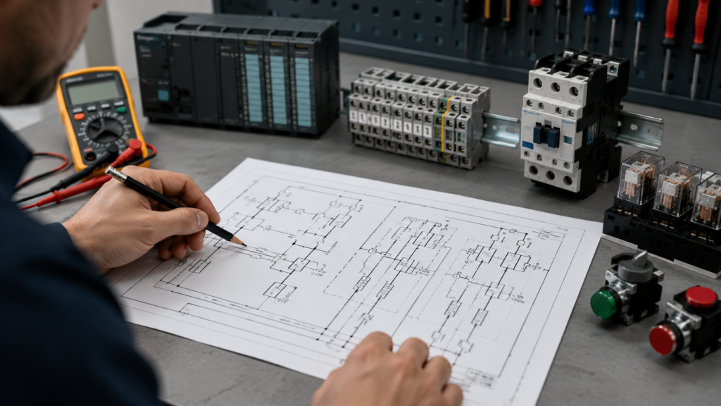
Industrial electrical schematics can look intimidating at first glance. A single drawing may contain dozens of wires, relay contacts, motor starters, sensors, circuit breakers, PLC inputs, and unfamiliar symbols.
The temptation is to start in the middle and follow whatever wire catches your eye.
That usually makes things worse.
A schematic becomes much easier to understand when you stop treating it like one giant drawing. Instead, break it into smaller circuits and read each section in a logical order.
This guide explains how to read an industrial electrical schematic step by step, even if you are still learning electrical control systems.
1. Identify the Type of Drawing
Before following any wires, check what kind of document you are looking at.
An industrial electrical documentation package may include:
- Single-line diagrams
- Power circuit diagrams
- Control circuit diagrams
- PLC wiring diagrams
- Terminal plans
- Cable schedules
- Panel layouts
- Input and output lists
These drawings serve different purposes.
A single-line diagram gives a simplified overview of power distribution. A control schematic shows how relays, contactors, sensors, and switches control the equipment. A panel layout shows where components are physically installed.
Do not expect every drawing to show both electrical operation and physical location.
2. Read the Title Block
The title block is usually found in the bottom-right corner of the page. It may contain:
- Drawing name
- Project name
- Drawing number
- Page number
- Revision number
- Designer or company name
- Date of issue
- Voltage level
This information matters more than many beginners realize.
You may be looking at an old revision that no longer matches the machine. A component may have been replaced, a wire number may have changed, or a safety circuit may have been redesigned.
Always check the revision before trusting the drawing completely.
3. Find the Main Power Source
Most industrial schematics are read from left to right or from top to bottom.
Begin by locating the incoming power source. Depending on the circuit, it may be labelled as:
- L1, L2, L3
- L and N
- +24 VDC and 0 VDC
- and –
- PE for protective earth
A three-phase motor circuit commonly starts with L1, L2, and L3. A PLC control circuit will often use 24 VDC.
Once you find the source, follow the circuit toward the load.
Think of it as tracing a path. Electrical current must leave the source, pass through protective and control devices, travel through the load, and return to the supply.
4. Separate the Power Circuit From the Control Circuit
One of the biggest improvements you can make is learning to separate power wiring from control wiring.
The power circuit supplies energy to the load. It may include:
- Circuit breakers
- Fuses
- Contactors
- Overload relays
- Motors
- Heaters
- Transformers
- Variable frequency drives
The control circuit determines when the load should operate. It may include:
- Pushbuttons
- Selector switches
- Relay coils
- Auxiliary contacts
- Sensors
- Safety relays
- PLC outputs
For example, a contactor may switch a three-phase motor in the power circuit. The contactor coil is controlled by a separate 24 VDC or 230 VAC control circuit.
The two sections are electrically connected through the contactor, but they serve different purposes.
5. Learn the Most Common Symbols
You do not need to memorise every electrical symbol immediately. Start with the components that appear most often.
Common reference letters include:
- Q for circuit breakers or switches
- F for fuses or protective devices
- K for relays and contactors
- M for motors
- S for switches and pushbuttons
- B for sensors
- T for transformers
- H for indicator lamps
- X for terminals
The exact reference system may vary between companies or drawing standards.
A contactor might be labelled K1. Its coil may appear on one page, while its main contacts and auxiliary contacts appear elsewhere. All of those symbols belong to the same physical device.
Matching reference numbers is therefore essential.
6. Understand Normal Component States
Electrical schematics normally show components in their resting state.
That usually means:
- The machine is not running
- Coils are de-energised
- Pushbuttons are not pressed
- Sensors are not activated
- Mechanical devices are in their normal position
A normally open contact is open when its relay coil is de-energised. It closes when the coil is energised.
A normally closed contact works in the opposite way. It is closed in the resting state and opens when the related device changes state.
The word “normal” does not necessarily mean normal machine operation. It refers to the unactuated or de-energised condition shown on the drawing.
This distinction prevents a lot of confusion.
7. Follow One Circuit at a Time
Never try to understand the complete machine in one pass.
Choose one load and trace only the circuit associated with it.
For example, suppose you want to understand how a conveyor motor starts. Locate the motor symbol, perhaps labelled M1. Then work backwards and identify:
- The overload relay
- The main contactor
- The protective circuit breaker or fuses
- The incoming power supply
- The contactor coil in the control circuit
- The conditions that energise that coil
This method gives you a clear story:
Power reaches the motor through the breaker, contactor, and overload relay. The contactor closes only when its coil receives power. The coil receives power only when the required control conditions are satisfied.
That is much easier to understand than jumping randomly between pages.
8. Read Series Conditions as “AND” Logic
Components connected in series must all allow current to pass.
Imagine a contactor coil controlled by:
- An emergency-stop contact
- A stop pushbutton
- An overload relay contact
- A start pushbutton
For the coil to energise, the emergency stop must be healthy, the stop button must be released, the overload must not be tripped, and the start command must be present.
In logical terms, series wiring behaves like an AND condition.
Every required contact must be closed.
This is useful during troubleshooting. If the coil is not receiving voltage, move through the series circuit one device at a time until you find where the voltage disappears.
9. Read Parallel Paths as “OR” Logic
Parallel branches provide more than one possible path for current.
A motor may be started either by a local pushbutton or by a PLC output. If these commands are wired in parallel, either one may energise the contactor coil.
Parallel wiring therefore behaves like an OR condition.
A common motor starter circuit also uses a contactor auxiliary contact in parallel with the start pushbutton. When the start button is pressed, the contactor energises. Its auxiliary contact then closes and keeps the coil powered after the button is released.
This is often called a holding circuit, seal-in circuit, or latching circuit.
10. Match Coils With Their Contacts
Relay and contactor contacts are often drawn far away from their coils.
A relay coil labelled K5 may have several contacts:
- K5.1
- K5.2
- K5.3
Some drawings use cross-references beside the coil or contact. These may point to another page and grid position, such as page 12, column 4.
Use those references.
Whenever a relay coil changes state, all contacts belonging to that relay change state as well. Normally open contacts close, while normally closed contacts open.
This relationship is central to understanding industrial control circuits.
11. Pay Attention to Wire and Terminal Numbers
Wire numbers help identify electrical connections, especially when a circuit continues across several pages.
Two wire sections carrying the same number are normally part of the same electrical connection, even if the line is not drawn continuously.
Terminal blocks are usually marked with a reference such as X1, X2, or X10. Individual terminal numbers may appear as:
- X1:1
- X1:2
- X1:3
This tells you exactly where a field cable, sensor, motor, or panel wire should be connected.
During troubleshooting, terminal numbers are often more useful than the visual arrangement of the schematic.
12. Use Page and Grid References
Large industrial schematics may contain hundreds of pages. Signals regularly continue from one page to another.
A reference beside a wire or component may tell you where the circuit continues. For example, a reference might point to page 25, grid B4.
Do not assume a wire ends simply because it disappears at the edge of the page.
Follow every continuation reference until you understand where the signal comes from and where it goes.
13. Identify Protection and Safety Devices
Look for devices that can intentionally interrupt the circuit.
These may include:
- Fuses
- Circuit breakers
- Motor overload contacts
- Emergency-stop contacts
- Guard switches
- Safety relays
- Thermal switches
- Pressure switches
- Phase monitoring relays
Protective contacts are commonly connected in series with a contactor or relay coil. When a fault occurs, the contact opens and removes power from the coil.
Safety circuits deserve extra care. Never bypass a safety contact simply because it prevents the machine from running. The open contact may be doing exactly what it was designed to do.
14. Translate the Drawing Into a Sequence
Once you have traced the circuit, describe its operation using plain language.
For example:
“When the emergency stop is released, the overload relay is healthy, and the stop button is closed, pressing the start button energises contactor K1. The K1 auxiliary contact closes and maintains power to the coil. The main K1 contacts close, supplying three-phase power to motor M1. Pressing the stop button interrupts the coil circuit and stops the motor.”
If you can explain the circuit in words, you probably understand it.
If the explanation still sounds confusing, return to the drawing and follow the circuit again.
15. Compare the Schematic With the Real Panel
Schematics show electrical relationships. They do not always show the exact physical position of components or wires.
Inside the control panel, confirm:
- Component reference labels
- Terminal numbers
- Wire numbers
- Cable markings
- Supply voltage
- Device condition
- Field wiring connections
The drawing and the panel should support each other.
When they do not match, document the difference. Industrial machines are frequently modified without the schematics being updated.
A Practical Troubleshooting Method
When a device is not operating, begin at the load and work backwards.
For a contactor coil that will not energise:
- Measure whether the correct voltage is present across the coil.
- If voltage is present but the coil does not energise, suspect the coil or mechanical contactor.
- If voltage is missing, trace the control circuit backwards.
- Check each series contact.
- Find the point where voltage is lost.
- Determine why that contact or device is open.
Do not simply replace components because they look old. Use the schematic to narrow the fault down logically.
Final Thoughts
Reading an industrial electrical schematic is not about staring at the entire drawing until it suddenly makes sense.
Start with the title block. Identify the supply. Separate power and control circuits. Choose one load, follow its circuit, match coils with contacts, and translate the operation into a simple sequence.
With practice, the mass of lines and symbols begins to look less like a puzzle and more like a map.
And that is exactly what an electrical schematic is: a map of how the machine is expected to behave.