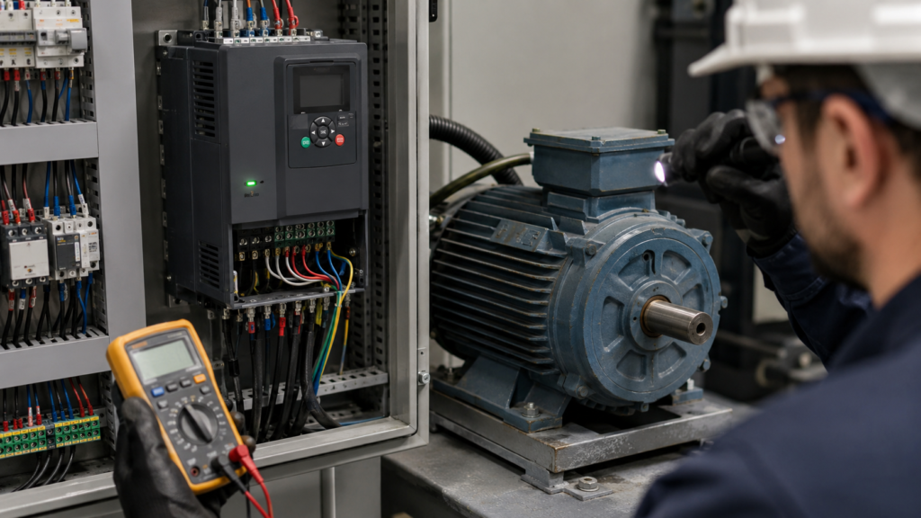
The PLC output is on. The VFD display says it has received a run command. There are no obvious faults, yet the motor remains completely still.
At first, this seems contradictory. Surely a run command should make the motor run?
Not necessarily.
A variable frequency drive normally requires several conditions before it produces voltage at its motor terminals. It may need a valid start command, a non-zero speed reference, an active run enable, a healthy safety circuit and permission from internal interlocks. If even one condition is missing, the drive may accept the command without rotating the motor.
The fastest way to find the problem is to separate the command, speed reference, drive status and motor output instead of changing parameters at random.
Work Safely Around the VFD
A VFD contains hazardous voltage even after its incoming supply has been switched off. Its internal DC bus capacitors can remain charged for several minutes.
Before touching motor cables, drive terminals or internal components:
- Isolate the incoming power
- Lock out the supply
- Wait for the discharge time stated by the manufacturer
- Confirm the absence of voltage with a suitable meter
- Follow the site’s electrical safety procedure
Do not disconnect a motor or output contactor while the drive is actively producing output.
Step 1: Confirm What “Run Command” Actually Means
Start by checking the drive’s status words or diagnostic screen.
There is an important difference between:
- A run signal being present at a terminal
- The drive recognising the run command
- The drive being ready to start
- The drive entering the running state
- The drive producing output frequency
- The motor physically rotating
A PLC output light only proves that the PLC has switched its output. It does not prove that the signal reached the correct VFD input or that the input is programmed as a start command.
Use the drive keypad or commissioning software to monitor the actual digital-input status.
If the assigned start input does not change when the PLC output changes, inspect:
- The control wiring
- The selected common terminal
- The PLC output type
- The VFD input logic
- The digital-input assignment
Do not continue with motor troubleshooting until the drive itself confirms that it sees the command.
Step 2: Look for Faults, Alarms and Inhibit Conditions
A drive does not always display a large red fault message when starting is blocked.
It may instead show a status such as:
- Not ready
- Start inhibited
- Switch-on disabled
- Coast stop active
- Quick stop active
- External fault
- Run enable missing
- Safety active
- Communication control missing
- Commissioning incomplete
Siemens documentation, for example, lists a missing ON command and other readiness conditions among the reasons a SINAMICS drive may not operate. A drive can therefore remain stopped without having a damaged power stage or motor.
Open the drive’s diagnostic menu rather than looking only at the main screen. Review active warnings, inhibit bits and the event history.
Some drives also require a new transition of the start signal after a fault reset. Leaving the run command permanently high may not restart the drive. Remove the command, reset the fault and then apply a fresh run command.
Step 3: Check the Speed Reference
A valid run command with a zero-speed reference often produces exactly what you are seeing: a drive in the running state and a stationary motor.
Monitor the drive’s active frequency or speed reference.
Possible reference sources include:
- Keypad potentiometer
- Analogue input
- PLC fieldbus value
- Preset frequency
- Motorised potentiometer function
- PID controller output
- Pulse input
- Internal fixed setpoint
The drive may be configured to receive its start command from terminals but its speed reference from fieldbus communication. In that arrangement, switching a digital start input is not enough. The PLC must also send a non-zero frequency reference.
Likewise, the PLC may be sending a speed value while the VFD is still configured to use an analogue input.
Schneider Electric’s drive-control documentation specifically requires a reference velocity other than zero before movement occurs.
Check both the configured reference source and the live reference value.
Step 4: Check Local and Remote Control Modes
Most VFDs can be controlled from more than one location:
- Local keypad
- Digital terminals
- PLC communication
- Remote operator panel
- Internal drive logic
If the drive is in local mode, it may ignore the PLC command. If it is in remote mode, the keypad’s start button may do nothing.
The display often shows a symbol or abbreviation such as:
- LOC
- REM
- HAND
- AUTO
- NET
- TERM
Confirm which command source is active.
As a diagnostic test, place the drive in local control and attempt to run the motor from the keypad at a low frequency. Make sure doing so is safe and that the machine can move without causing injury or damage.
If the motor runs locally, the VFD power stage, motor cable and motor are probably functional. Concentrate on external commands, control-source parameters and PLC logic.
If it still does not run locally, the fault is more likely inside the drive configuration, safety circuit, motor connection or mechanical system.
Step 5: Verify the Start and Direction Logic
Different drives can use different command arrangements.
Common control modes include:
Two-Wire Control
A maintained signal commands the drive to run. Removing the signal stops it.
Three-Wire Control
Separate momentary start and stop signals are used. The stop input usually needs to remain healthy before a start pulse is accepted.
Forward and Reverse Commands
One input may command forward movement while another commands reverse movement.
Run Enable Plus Direction
One signal enables operation, while another selects direction.
If the VFD is configured for three-wire control but the panel is wired as two-wire control, the run input may appear active without completing the required start sequence.
Also check whether forward and reverse commands are active at the same time. Many drives respond by stopping, ignoring both commands or generating an alarm.
Step 6: Check PNP, NPN and Digital-Input Common Wiring
Many commissioning problems come from a mismatch between sourcing and sinking control logic.
A VFD input may expect:
- +24 V to activate the input
- 0 V to activate the input
- An external control supply
- The VFD’s internal 24 V supply
The drive may describe this using terms such as:
- PNP
- NPN
- Source
- Sink
- Positive logic
- Negative logic
If the PLC uses PNP outputs while the drive is wired or configured for NPN logic, its input LEDs may behave unexpectedly or never activate.
Check the exact VFD wiring diagram. Confirm that the input common, PLC common and control supply are connected correctly. Do not assume every terminal marked “COM” serves the same purpose.
Step 7: Inspect Safe Torque Off
Safe Torque Off, usually abbreviated as STO, prevents the VFD from producing motor torque.
The drive control electronics may remain powered. Its display may operate normally, and communication with the PLC may continue. However, the power stage will not drive the motor while STO is active.
Check:
- Emergency-stop buttons
- Guard switches
- Safety relay outputs
- STO terminal voltage
- Dual-channel STO wiring
- Safety PLC status
- Loose terminal links
- Safety-related drive diagnostics
Many drives require both STO channels to be healthy.
Never bridge or bypass STO simply to make the motor run. Diagnose why the safety permission is missing and restore the circuit according to the approved design.
Step 8: Verify Run Enable and External Interlocks
Some applications use a separate enable input in addition to the normal start command.
The enable may come from:
- A safety relay
- A pressure switch
- A lubrication system
- A thermal protection relay
- A motor fan contact
- A brake feedback contact
- A PLC permissive
- An external fault contact
- A damper or valve limit switch
ABB drive documentation shows examples where start enable and run enable signals are separate conditions in the starting sequence.
Monitor every programmed digital input and interlock status. A contact that looks unrelated may be the final condition preventing the drive from starting.
Step 9: Check Fieldbus Control Words
When a PLC controls the VFD over PROFINET, PROFIBUS, EtherNet/IP, Modbus or another network, a simple run bit may not be enough.
Many drive telegrams use a control word containing separate bits for:
- ON/OFF command
- Coast-stop release
- Quick-stop release
- Operation enable
- Fault acknowledgement
- Direction
- Setpoint enable
The PLC may be setting the ON bit while leaving operation enable or quick-stop release inactive.
Compare the control word sent by the PLC with the drive’s status word. The status word normally reveals whether the drive is:
- Ready to switch on
- Ready for operation
- Operation enabled
- Faulted
- Inhibited
- At zero speed
Also confirm that the drive is actually configured to accept commands from the communication network. A healthy network connection does not automatically mean the fieldbus is the active command source.
Step 10: Observe Output Frequency, Voltage and Current
The drive’s live values can quickly tell you where the problem is.
Output Frequency Remains at 0 Hz
The drive has not accepted the complete start sequence, the speed reference is zero or an inhibit remains active.
Output Frequency Increases but Output Current Is Near Zero
Possible causes include:
- Motor cable disconnected
- Output contactor open
- Broken motor winding
- Incorrect motor connection
- Motor not actually connected to that VFD
Output Frequency and Current Increase, but the Motor Does Not Turn
Possible causes include:
- Mechanical brake not releasing
- Motor shaft or gearbox jammed
- Load mechanically locked
- Incorrect motor data
- Current or torque limit set too low
- Motor connected incorrectly
- Motor producing insufficient starting torque
Do not repeatedly command a stalled motor to start. High current can damage the motor, drive or mechanical equipment.
Step 11: Inspect the Motor-Side Contactor
Some systems install a contactor between the VFD and motor.
If that contactor does not close, the drive may enter the running state while the motor receives no voltage.
Check the contactor’s:
- Coil voltage
- Auxiliary feedback contact
- Mechanical operation
- Main contacts
- Interlocking logic
The contactor should normally be closed before the VFD begins producing output. Opening or closing it while the drive is running can create voltage spikes and drive faults.
If several motors share one VFD, verify that the correct motor contactor has been selected and closed.
Step 12: Check the Motor Nameplate Parameters
Incorrect motor data can prevent successful commissioning or produce too little torque to move the load.
Verify:
- Rated motor voltage
- Rated current
- Rated frequency
- Rated speed
- Rated power
- Power factor
- Motor connection
- Control method
Pay particular attention to the motor’s star and delta voltage ratings.
A motor marked 230/400 V is normally connected in star on a 400 V supply. A motor marked 400/690 V is normally connected in delta when operated from a 400 V VFD.
Follow the motor manufacturer’s nameplate and the VFD manual rather than relying on a general rule alone.
Some vector-control applications also require motor identification or autotuning before normal operation. During certain identification routines, the first start command may perform measurements instead of accelerating the motor normally.
Step 13: Check the Mechanical Brake and Load
The motor may be receiving power but physically unable to move.
This is common with:
- Hoists
- Lifts
- Cranes
- Geared motors
- Servo applications
- Conveyors with backstops
- Motors fitted with spring-applied brakes
Confirm that the brake coil receives the correct voltage and that the brake releases before torque is applied.
If permitted by the equipment procedure, isolate the motor from the mechanical load and test it independently. Do not uncouple machinery without considering stored energy, gravity and unexpected movement.
A seized gearbox, jammed conveyor or failed brake can look exactly like a VFD problem.
A Fast Troubleshooting Sequence
Use this order when a VFD receives a run command but the motor does not start:
- Confirm that the drive sees the start input.
- Read active faults, warnings and inhibit conditions.
- Check that the speed reference is above zero.
- Verify local or remote control mode.
- Confirm the selected two-wire or three-wire command logic.
- Check PNP/NPN input wiring.
- Verify STO and safety permissions.
- Check run-enable signals and external interlocks.
- Inspect the fieldbus control and status words.
- Monitor output frequency, voltage and current.
- Check the motor contactor and cable.
- Verify motor nameplate data and terminal connections.
- Inspect the mechanical brake and driven equipment.
Final Thoughts
A run command is only one part of the VFD starting sequence.
The drive must also be ready, enabled and free from safety or stop conditions. It needs a valid speed reference, the correct control source and an electrically connected motor that is free to rotate.
Start with the live drive status rather than the PLC output light. Then follow the chain from command to enable, output frequency, motor current and finally mechanical movement.
That approach usually exposes the missing condition without unnecessary parameter changes—or an expensive VFD replacement that was never needed.