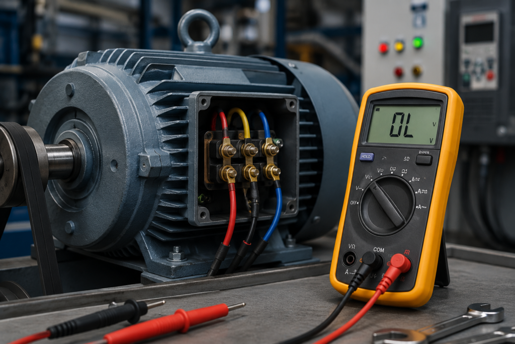
A three-phase motor does not always stop immediately when one phase is lost.
Sometimes it refuses to start and only hums. In other cases, the motor keeps turning because the shaft was already moving when the phase disappeared. It may sound rough, lose torque, draw heavily unbalanced current and become dangerously hot.
This condition is known as single phasing.
It is one of those faults that can appear harmless for a few minutes while quietly damaging the motor. The machine still moves, so production continues. Meanwhile, the remaining windings carry abnormal current and the motor temperature climbs.
Finding single phasing requires more than checking whether the shaft rotates. You need to inspect the complete circuit and compare all three phases under operating conditions.
What Is Single Phasing?
Single phasing occurs when one conductor or electrical path in a three-phase motor circuit becomes open.
Instead of receiving three healthy phases, the motor is left connected through only two effective supply paths.
The missing phase can occur:
- Before the motor starter
- Inside the starter
- After the overload relay
- Inside the motor cable
- At the motor terminals
- Inside a motor winding
The motor’s behaviour depends on when the phase is lost.
A stationary motor generally cannot develop a proper rotating magnetic field on only two phases. It may hum, vibrate or fail to accelerate.
A motor that is already running may continue turning because its rotor has momentum and the remaining phases still produce some torque. That does not make continued operation safe.
Phase loss can cause a major increase in current through the remaining motor circuit and can damage both the rotor and stator if protection does not disconnect the supply.
Common Symptoms of Single Phasing
Single phasing does not look identical in every application, but several warning signs appear repeatedly.
The Motor Will Not Start
When one phase is missing before startup, the motor may:
- Hum loudly
- Vibrate without rotating
- Start only when unloaded
- Turn slowly
- Trip the overload relay
- Draw high current
Do not repeatedly press the start button. A stalled motor has very little cooling and can overheat quickly.
The Motor Keeps Running but Loses Torque
If phase loss happens while the motor is already operating, it may continue to rotate.
You may notice:
- Reduced torque
- Slower acceleration
- Speed dropping under load
- A conveyor struggling with normal material
- A pump producing less flow or pressure
- A compressor failing to reach pressure
- Overload trips after several minutes
The motor may appear almost normal with no mechanical load. The problem becomes more obvious when the machine begins doing real work.
The Motor Becomes Hot
Current in the remaining phases usually becomes severely unbalanced.
This creates extra heating even when the average current does not initially look extreme. Phase-current imbalance can produce braking torque and significant temperature rise, leading to premature motor deterioration.
Other symptoms can include:
- A burnt insulation smell
- Discoloured motor terminals
- Excessive fan noise
- Hot contactor terminals
- Repeated thermal-overload trips
The Motor Sounds Different
A single-phasing motor may produce:
- A deeper humming sound
- Uneven magnetic noise
- Pulsating vibration
- Rhythmic mechanical movement
- Contactor or cable buzzing
Experienced technicians often notice the sound before the protection trips, but sound alone is not a reliable test.
What Causes Single Phasing?
The missing phase can originate almost anywhere between the power source and the motor windings.
Blown Fuse
One fuse may operate while the other two remain intact.
This can happen because of:
- A short circuit
- An incorrectly sized fuse
- Loose fuse-holder contacts
- Age or thermal damage
- Previous motor overload
- A downstream cable fault
Never check a fuse only by looking at it. Test it electrically.
Failed Contactor Pole
A contactor can pull in normally while one main pole fails to conduct.
Possible causes include:
- Burned contacts
- A welded or damaged contact mechanism
- Mechanical misalignment
- Loose power terminals
- Severe contact erosion
The coil and auxiliary contacts may still operate, misleading you into thinking the complete contactor is healthy.
Loose or Burned Connection
A loose terminal can behave normally at low current but open or develop a large voltage drop under load.
Common locations include:
- Circuit-breaker terminals
- Fuse holders
- Contactor terminals
- Overload-relay terminals
- Local isolators
- Cable joints
- Motor terminal boxes
Heat marks and damaged insulation are important clues, but not every high-resistance connection is visibly burned.
Broken Motor Cable
Conductors can fail because of:
- Repeated flexing
- Mechanical damage
- Vibration
- Water ingress
- Poorly installed cable glands
- Corroded joints
- Damage inside an energy chain
An intermittent conductor may reconnect when the machine moves or the cable is disturbed, making the fault difficult to reproduce.
Open Motor Winding
The external supply may be healthy while one stator winding is open internally.
Possible causes include:
- Burned winding wire
- A failed internal joint
- Broken terminal lead
- Previous overheating
- Poor repair work
The motor should remain isolated until the winding condition is properly tested.
Upstream Supply Failure
The fault may exist before the machine panel.
Examples include:
- A failed transformer phase
- An open distribution fuse
- A damaged breaker pole
- A loose busbar connection
- A utility supply problem
Check whether other three-phase loads in the same area show similar symptoms.
Step 1: Stop the Motor
When single phasing is suspected, stop the motor as soon as it is safe to do so.
Do not keep restarting it to see whether the fault disappears. Continued operation can cause winding damage even when the motor has not yet produced smoke or a strong burning smell.
Allow the motor to cool before carrying out further tests if it is unusually hot.
Step 2: Perform a Visual Inspection
Isolate and lock out the supply before touching the circuit.
Inspect:
- Fuses and fuse holders
- Circuit-breaker terminals
- Contactor main contacts
- Overload-relay terminals
- Cable insulation
- Motor terminal links
- Local isolators
- Cable glands
- Motor windings for signs of overheating
Look for darkened copper, melted plastic, loose screws, cracked terminals and the smell of overheated insulation.
A visual inspection is useful, but it cannot prove that all phases are electrically intact.
Step 3: Measure All Three Line Voltages
Measure:
- L1 to L2
- L2 to L3
- L3 to L1
Begin at the incoming supply and then move through the motor circuit.
Possible test points include:
- Incoming breaker
- Fuse output
- Contactor input
- Contactor output
- Overload-relay output
- Motor terminals
Compare readings at the same moment and under the same conditions.
When the contactor is open, voltage measurements can sometimes be deceptive. Voltage may appear through connected windings, indicator circuits or electronic equipment even though one conductor cannot carry real load current.
Whenever practical and safe, compare the voltages while the motor circuit is energised and loaded.
A large voltage drop across one fuse, contactor pole or terminal identifies the defective part of the circuit.
Step 4: Measure Current in Every Phase
Current measurements are often more revealing than voltage readings.
Use a clamp meter to measure:
- Current in L1
- Current in L2
- Current in L3
Do not measure only one conductor.
Typical single-phasing results include one phase at or near zero current while the remaining phases carry increased current. Electronic motor protection devices commonly detect phase failure by comparing the lowest measured phase current with the highest.
Schneider Electric’s current-phase-loss protection, for example, can identify a condition when one motor phase falls below a small percentage of the configured full-load current.
Compare the readings with the motor nameplate and overload-relay setting. Stop the test immediately if current is dangerously high or the motor cannot accelerate.
Step 5: Test the Fuses Properly
After isolation, remove and test each fuse using a continuity or resistance function.
A good fuse should show very low resistance. An open fuse will show no continuity.
Also inspect the fuse holder. A healthy fuse inside a damaged holder can still create an open or high-resistance phase.
If one fuse has operated, do not simply install another and restart the machine. Determine why it failed. The fuse may have responded to a cable fault, damaged winding or short circuit.
Replace fuses with the correct type, voltage rating and current rating.
Step 6: Test the Contactor Poles
With the circuit isolated, inspect and test all three main poles.
When the contactor is manually or electrically closed under an approved test procedure, each pole should show low resistance.
During an energised test, compare the voltage drop across:
- L1 to T1
- L2 to T2
- L3 to T3
A healthy closed contactor should have only a small voltage drop across each pole. A large voltage across one closed pole indicates that it is not conducting correctly.
Do not assume the contactor is good simply because it clicks.
Step 7: Check the Overload Relay
Some overload relays provide phase-failure sensitivity, while basic protection may react mainly to heating caused by the increased current.
Verify:
- The correct motor current setting
- Whether phase-loss protection is included
- That all conductors pass through the required sensing paths
- That no power terminal is loose or damaged
- Whether the relay actually tripped
- The configured trip delay
ABB and other manufacturers offer overload relays and manual motor starters specifically designed to protect against both overload and phase failure.
Do not bypass an overload relay because it keeps tripping. It may be the only device preventing the motor from burning out.
Step 8: Test the Motor Cable
Disconnect the cable at both ends before resistance or insulation testing.
Check each conductor for:
- Continuity
- Similar conductor resistance
- Short circuits between phases
- Short circuits to earth
- Insulation breakdown
Flex or move sections of the cable only where it is safe to do so. An intermittent break may appear only when the conductor is bent.
Use the appropriate test voltage for insulation-resistance testing and disconnect sensitive electronic equipment first.
Step 9: Compare Motor Winding Resistance
With the motor isolated and terminal links removed, measure the resistance of each winding.
For a six-terminal motor, compare:
- U1 to U2
- V1 to V2
- W1 to W2
The three readings should be reasonably similar.
One open reading indicates a broken winding path or connection. A noticeably different resistance may suggest a winding fault, poor terminal joint or measurement problem.
Large motors have very low winding resistance, so an ordinary multimeter may not provide enough accuracy. A low-resistance ohmmeter may be required.
Also perform insulation-resistance testing between each winding and earth according to the motor manufacturer’s procedure.
Step 10: Check the Protection Design
Once the fault is repaired, consider whether the motor has adequate protection against another phase loss.
Useful protective devices include:
- Phase-monitoring relays
- Phase-sequence and phase-failure relays
- Phase-sensitive overload relays
- Electronic motor-protection relays
- Motor-management systems
- VFD or soft-starter phase-loss protection
Voltage-monitoring relays detect supply-side phase loss. Current-monitoring protection can also detect faults occurring after the voltage relay, such as an open contactor pole or broken motor conductor.
The best arrangement depends on the motor size, application and consequences of failure.
A Fast Troubleshooting Sequence
When single phasing is suspected:
- Stop the motor.
- Lock out and inspect the complete circuit.
- Measure all three line-to-line voltages.
- Measure current in all three phases.
- Test every fuse and fuse holder.
- Check all three contactor poles.
- Inspect the overload relay and its settings.
- Test the motor cable.
- Compare the motor winding resistances.
- Verify phase-loss protection before restarting.
Final Thoughts
A rotating shaft does not prove that a three-phase motor is receiving three healthy phases.
A running motor can lose one phase, continue turning and still suffer serious internal heating. The clearest warning signs are reduced torque, abnormal sound, current imbalance, overheating and repeated overload trips.
Measure all three phases, not just one. Test the circuit in sections, beginning at the supply and working toward the motor.
Most importantly, do not treat single phasing as a minor performance problem. It is a motor-damaging condition that should be investigated immediately.