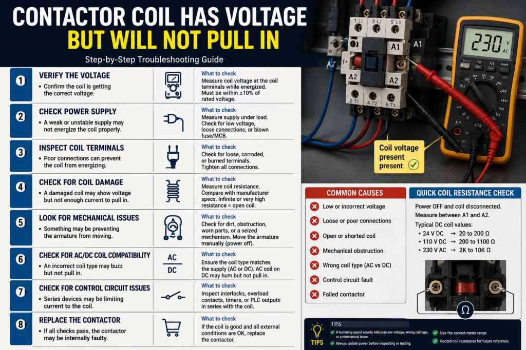
You press the start button, the PLC output turns on, and your multimeter shows voltage at the contactor coil. Yet the contactor does not move.
At first glance, the diagnosis seems obvious: the contactor must be faulty.
Sometimes it is. Quite often, though, the voltage measurement is misleading. The wrong coil may have been installed, the voltage may collapse under load, or a high-resistance connection may allow a digital meter to display full voltage without supplying enough current to energise the coil.
The quickest way to find the fault is to measure directly across the coil while it is supposed to pull in, then separate the control-circuit problem from the contactor itself.
Work Safely Around the Contactor
Contactors are usually installed inside panels containing hazardous control and power voltages.
Before removing the coil, checking resistance or attempting to move the mechanism:
- Isolate and lock out the panel
- Verify the absence of voltage
- Disconnect stored-energy sources
- Confirm that the connected motor or machine cannot start
- Follow the equipment manufacturer’s maintenance instructions
Never manually force a contactor closed while its main circuit is energised. This can start machinery unexpectedly and may bypass normal electrical or safety interlocks.
Step 1: Measure Directly Across A1 and A2
The first measurement should be taken directly across the coil terminals:
- One probe on A1
- One probe on A2
Take the reading while the start command is active and the contactor is expected to close.
Do not measure only from A1 to earth or A1 to neutral. That may show that voltage reaches one side of the coil, but it does not prove that a complete circuit exists through A2.
For example, A1 may have 230 V to neutral while A2 is also sitting close to 230 V because of a broken neutral conductor. The voltage across A1 and A2 would then be close to zero, so the coil cannot energise.
The voltage that matters is the voltage across the coil.
Step 2: Read the Actual Coil Rating
Check the voltage printed on the coil or contactor.
Possible ratings include:
- 24 V DC
- 24 V AC
- 48 V AC
- 110 V AC
- 120 V AC
- 220–240 V AC
- 230 V AC
- Wide-range AC/DC electronic coils
The main contact rating does not tell you the coil voltage. A contactor capable of switching a 400 V motor could still have a 24 V DC control coil.
Schneider Electric notes that AC and DC TeSys contactors use different coil formats and that the coil voltage marking may be located on the top or front of the device, depending on its design.
Compare four details:
- Rated voltage
- AC or DC
- Frequency for an AC coil
- Permitted operating range
A 24 V DC supply will not correctly operate a 24 V AC coil merely because both labels say 24 V. Conventional AC and DC coils are designed differently.
Step 3: Check Whether the Voltage Is High Enough
A contactor requires more magnetic force to pull in than it needs to remain closed.
For many conventional contactors, the acceptable operating range begins around 85% of the rated coil voltage, although the exact value must be checked in the manufacturer’s data. ABB states that conventional contactors commonly operate within 85% to 110% of rated coil voltage, while a current Siemens product lists the same 0.85–1.1 operating range.
This means a 230 V coil may not pull in reliably if it receives only 180 V during the closing attempt.
Do not judge the supply from a measurement taken when the coil is disconnected. Measure while the coil is connected and the start command is active.
Low voltage during pull-in can cause:
- Failure to close
- Slow armature movement
- Chattering
- Contact bounce
- Coil overheating
- Premature contact damage
A conventional AC coil has much lower impedance while the magnetic circuit remains open. If the contactor cannot close, excessive coil current may continue long enough to overheat or burn the winding.
Do not leave a humming contactor energised while you continue troubleshooting.
Step 4: Watch for Voltage Collapse
Suppose the meter shows 24 V before the coil is connected but only 9 V when the start command is applied.
The coil may be healthy. The control circuit simply cannot provide its required pull-in current.
Possible causes include:
- A weak control transformer
- An undersized 24 V power supply
- Excessive cable length
- Loose terminals
- Corroded pushbutton contacts
- A failing relay contact
- A damaged PLC output
- Excessive resistance in a safety relay output
- Several contactors energising simultaneously
- An incorrectly selected interposing relay
Larger contactors can require significantly more power during pull-in than while held closed. Siemens data for one contactor, for example, lists 280 VA during pickup but only about 32 VA while held.
This sudden demand can reveal a control supply that appears healthy at no load.
Measure the voltage:
- At the control power supply
- Before the stop and safety circuit
- At the PLC or relay output
- At A1 and A2
The point where the voltage suddenly falls usually identifies the high-resistance connection or undersized supply.
Step 5: Do Not Trust a High-Impedance Voltage Reading Alone
A modern digital multimeter draws very little current.
Because of that, it can show nearly full voltage through:
- Leakage from an electronic output
- A suppression component
- Capacitive coupling between cables
- A badly burned contact
- A nearly open connection
- An indicator lamp or electronic module
The voltage exists, but the circuit may not be able to deliver useful current.
When permitted by the equipment procedure, confirm the measurement using a suitable low-impedance tester or an approved test load. Do not improvise with exposed lamps, loose resistors or unprotected wires.
Another useful test is to compare voltage across each closed control contact. A healthy closed contact should have very little voltage across it. A large voltage drop across a closed pushbutton, relay contact or PLC output indicates unwanted resistance.
Step 6: Check the Return Side of the Coil
Technicians naturally follow the switched conductor toward A1, but the fault is often on A2.
Depending on the circuit, A2 may return through:
- Neutral
- 0 V DC
- Another phase
- A safety relay
- A PLC output
- A control transformer
- An electronic switching module
A broken neutral or 0 V conductor can produce confusing readings. You may measure the expected voltage from A1 to earth while the coil still has no complete return path.
Measure both sides against the control reference, then verify the voltage directly across A1 and A2.
Step 7: Check for Reversed Polarity
Polarity usually does not matter for a plain DC electromagnetic coil.
It can matter when the contactor includes:
- An LED indicator
- A built-in diode
- An electronic wide-range coil
- A DC surge suppressor
- A polarity-sensitive interface module
Terminals may be marked A1+ and A2−.
If polarity is reversed, the contactor may fail to operate, or a protection device may short the control supply. Follow the terminal markings and the manufacturer’s diagram.
Step 8: Isolate and Test the Coil
After locking out and verifying zero voltage, disconnect at least one coil conductor.
Measure resistance across A1 and A2.
Open-Circuit Reading
An infinite or open reading usually indicates:
- A burned coil winding
- A broken internal connection
- A failed thermal link
- A disconnected replaceable coil
Measurable Resistance
A resistance reading proves that the coil has continuity, but it does not prove that the coil is healthy.
Coil resistance varies widely with voltage rating, contactor size, temperature and whether the coil contains electronic components. Compare the reading with the manufacturer’s data or with an identical known-good contactor.
Do not insulation-test an electronic coil unless the manufacturer explicitly provides a suitable procedure.
Step 9: Check for Mechanical Binding
If the correct voltage remains directly across the coil but the contactor does not even attempt to move, isolate the power and inspect the mechanism.
Possible mechanical causes include:
- Dirt inside the magnetic assembly
- Rust or corrosion
- A foreign object blocking movement
- Melted plastic
- A damaged return spring
- Misaligned auxiliary-contact blocks
- Incorrectly installed accessories
- Welded main contacts
- A deformed armature
- Severe contact wear
With the contactor isolated, the armature should move freely according to its design and return normally when released.
Schneider’s motor-control troubleshooting guidance recommends checking the armature and contact assembly for free movement when a contactor fails to close.
Do not lubricate magnetic pole faces unless the manufacturer specifically instructs you to do so. Oil attracts dust and can prevent the magnetic surfaces from closing correctly.
Step 10: Listen to What the Contactor Is Doing
The sound can provide a useful clue.
Completely Silent
Likely causes include:
- No true voltage across the coil
- Open coil
- Wrong coil voltage
- Incorrect polarity on an electronic coil
- Severe mechanical blockage
Quiet Click but No Full Movement
Possible causes include:
- Low voltage
- Voltage collapse
- Mechanical obstruction
- Damaged armature
- An accessory preventing travel
Loud Humming or Chattering
Common causes include:
- Low control voltage
- Loose control wiring
- Intermittent PLC or relay output
- Dirty or corroded magnet faces
- Broken AC shading ring
- Mechanical misalignment
ABB explains that contaminated or deformed pole surfaces can cause AC hum, while a broken shading ring can cause severe chatter and normally requires replacement of the contactor.
Step 11: Remove Auxiliary Accessories
Front- and side-mounted accessories can interfere with contactor operation when damaged or installed incorrectly.
Temporarily remove nonessential accessories after isolation, such as:
- Auxiliary-contact blocks
- Mechanical interlocks
- Pneumatic timers
- Latching mechanisms
- Surge suppressors
- Interface modules
Then check whether the bare contactor mechanism moves freely.
On reversing starters, inspect the mechanical interlock carefully. If the opposite contactor has not fully released, the interlock may correctly prevent this contactor from closing.
Never defeat a mechanical interlock while the starter is energised.
Step 12: Test With a Known-Good Control Supply
When the wiring and measured voltage remain questionable, disconnect the contactor from the control circuit and test it using a correctly rated, protected control supply.
Only perform this test when:
- The main power circuit is isolated
- The load cannot start
- The test voltage exactly matches the coil
- The temporary circuit is fused or otherwise protected
- The procedure is permitted on site
If the contactor pulls in correctly on the test supply, the fault is in the machine’s control circuit.
If it still refuses to pull in with the correct voltage, replace the coil or complete contactor as appropriate.
Fast Troubleshooting Sequence
When a contactor coil has voltage but will not pull in:
- Measure directly across A1 and A2.
- Read the actual coil voltage and AC/DC rating.
- Measure the voltage while the coil is connected.
- Watch for voltage collapse during pickup.
- Check both the supply and return sides.
- Inspect closed control contacts for voltage drop.
- Confirm polarity where electronic components are present.
- Isolate and measure coil continuity.
- Check the armature for free movement.
- Remove damaged auxiliary accessories.
- Test with a known-good protected supply.
- Replace the coil or contactor if the correct voltage is present but it still cannot operate.
Final Thoughts
“Voltage at the coil” is not a complete diagnosis.
You need the correct voltage across A1 and A2, with the coil connected, at the exact moment the contactor is trying to close.
If that voltage is low or collapses, investigate the control supply and every connection in the circuit. If the correct voltage remains present, check the coil, polarity and mechanical movement.
Most importantly, do not let a contactor sit and chatter. A small voltage problem can quickly become a burned coil and damaged main contacts.