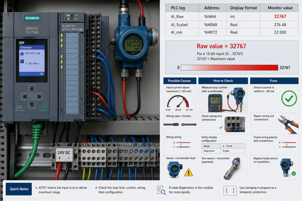
You open a watch table in TIA Portal and find that an analog input is showing 32767.
The transmitter is supposed to measure pressure, temperature, level or flow, so a value this high can look like a process reading beyond full scale. In many Siemens systems, however, 32767 is not a normal measurement.
It is usually a special value indicating that the analog channel cannot provide a valid process value.
The difficult part is that 32767 does not always identify one specific fault. Depending on the Siemens module and channel configuration, it may indicate a wire break, input overflow, missing module power, a deactivated channel or another diagnostic condition.
What Does 32767 Mean?
The decimal value 32767 is the largest positive number that can be stored in a signed 16-bit INT.
In hexadecimal, it is:
16#7FFF
Most Siemens analog input ranges use 27648 as the top of the normal rated measurement range. Values between 27649 and 32511 may represent overrange, while values from 32512 to 32767 belong to the overflow region on many S7-1200 analog modules.
Therefore:
27648normally represents 100% of the configured range- Values above
27648indicate that the signal is beyond its normal measuring range 32767often means overflow or a channel diagnostic condition
Do not scale 32767 into engineering units as though it were a valid measurement.
32767 Does Not Always Mean the Same Thing
Siemens analog modules do not all report faults in exactly the same way.
On some S7-1200 SM 1231 current-input modules, both a wire break and an overflow condition can return 32767. Siemens specifically notes that additional diagnostic logic may be needed to determine which condition occurred.
Other module types may use 32767 for:
- Wire break
- Sensor open circuit
- Positive overflow
- Deactivated channel
- Missing module supply
- Thermocouple or RTD diagnostic error
- Input signal above the permitted range
Always check the manual for the exact CPU, signal board or analog module order number.
Cause 1: Broken 4–20 mA Loop
A broken current loop is one of the most common causes.
Possible break points include:
- Failed transmitter power supply
- Blown loop fuse
- Loose terminal
- Broken field cable
- Disconnected transmitter
- Incorrect polarity
- Failed intrinsic-safety barrier
- Open circuit inside the transmitter
On supported Siemens 4–20 mA channels, a wire break may cause the input value to jump to 32767, even when the wire-break diagnostic alarm itself has not been enabled. Siemens documents that the wire-break value 32767 can be returned regardless of whether the corresponding alarm is activated.
How to Test It
Measure the actual loop current using a loop calibrator or a multimeter inserted correctly in series.
Also measure the available voltage:
- At the 24V DC supply
- At the transmitter terminals
- Across the PLC analog input
- Across any isolator or barrier
If the loop current is approximately 0 mA, work through the complete series circuit until you find where current stops flowing.
Do not connect a multimeter set to current mode directly across the 24V supply. That creates a short circuit.
Cause 2: Signal Above the Measurement Range
The input may genuinely be receiving more voltage or current than its configured range allows.
For a common Siemens current input:
27648represents the top of the rated range27649–32511represents overrange32512–32767represents overflow
For S7-1200 G2 analog inputs, Siemens shows 32767 when the measured current exceeds the module’s specified overflow threshold. The exact physical threshold depends on whether the channel is configured for 0–20 mA or 4–20 mA.
Possible causes include:
- Transmitter output above 20 mA
- Incorrect transmitter scaling
- Wrong analog range selected
- Voltage connected to a current input
- Incorrect wiring
- Failed transmitter electronics
- Process pressure or temperature far above range
- Loop calibrator set too high
Measure the real input signal before assuming that the PLC module is defective.
Cause 3: Channel Is Deactivated
A disabled or deactivated analog channel may also report 32767.
Siemens states that deactivated analog input channels can return 32767. A technician may therefore spend time checking field wiring even though the channel was simply disabled in the hardware configuration.
Open the device configuration and check:
- Whether the channel is enabled
- Which measuring type is selected
- Which measuring range is selected
- Whether the hardware configuration has been downloaded
- Whether the correct channel address is being monitored
Also confirm that the PLC tag points to the intended input word. You may be monitoring an unused channel rather than the connected transmitter.
Cause 4: Missing Module Power
Some analog modules require separate load or transmitter power.
If that supply is missing, the module may report an overflow value on one or more channels. Siemens documents that an analog module with a power-supply diagnostic error can report 32767 for all input channels.
Check:
- Module supply voltage
- Terminal wiring
- Fuse condition
- Power jumper or base-unit configuration
- Status LEDs
- TIA Portal diagnostic buffer
- Whether all channels failed at the same time
If every channel on one module suddenly shows 32767, shared module power or module-level diagnostics are more likely than several transmitters failing simultaneously.
Cause 5: Wrong Channel Configuration
A channel configured incorrectly may interpret a healthy electrical signal as an invalid value.
Common mistakes include:
- 4–20 mA transmitter on a voltage input
- 0–10 V sensor on a current input
- RTD channel configured for a thermocouple
- Wrong RTD resistance type
- Incorrect two-, three- or four-wire selection
- Wrong thermocouple type
- Disabled reference-junction compensation
- Unused current channel configured for wire-break monitoring
For selected S7-1200 signal boards, Siemens recommends configuring unused current channels as 0–20 mA or disabling wire-break reporting to avoid unwanted open-wire diagnostics.
Compare the channel configuration with the sensor’s datasheet and actual wiring.
Cause 6: Open RTD or Thermocouple Circuit
Temperature modules can also use 32767 to report a sensor or wiring failure.
Possible causes include:
- Broken thermocouple wire
- Disconnected RTD
- Loose compensation cable
- Incorrect terminal connection
- Failed temperature probe
- Open internal sensor element
- Wrong two-, three- or four-wire arrangement
Siemens analog diagnostic tables show 32767 for wire break and positive overflow on supported RTD and thermocouple inputs.
Disconnect the sensor only after isolating the circuit where required. Test thermocouple continuity or compare RTD resistance with the expected value at the current temperature.
Do not insulation-test a sensor while it remains connected to the analog module.
Check the TIA Portal Diagnostics
The raw value alone may not tell you whether the fault is wire break, overflow or missing supply.
Open:
Online & diagnostics → Diagnostic buffer
Also inspect:
- Module information
- Channel diagnostics
- Device status
- Hardware configuration
- Module LEDs
- Diagnostic interrupts
On certain S7-1200 modules, wire break and overflow both return 32767, so the diagnostic information is needed to separate them. Siemens also notes that a module can contain multiple channel errors while initially reporting only the first one to the CPU.
Fix the first reported fault, then check whether another diagnostic appears.
Test the PLC Input With a Calibrator
A loop calibrator is one of the fastest ways to separate a field-device problem from a PLC problem.
For a 4–20 mA channel:
- Disconnect the field transmitter according to the approved procedure.
- Connect the calibrator to the analog input.
- Generate 4 mA.
- Confirm that the raw value is near the configured minimum.
- Generate 12 mA.
- Confirm that the value is near the midpoint.
- Generate 20 mA.
- Confirm that the value is near
27648.
If the PLC reads the calibrator correctly, the module and configuration are probably functional. Continue troubleshooting the transmitter, loop supply and field cable.
If the channel still displays 32767, investigate the hardware configuration, module power, terminal wiring or the input module itself.
Prevent 32767 From Becoming a False Process Value
Your PLC program should reject special analog values before scaling them.
A basic example in SCL could look like this:
#AnalogSignalValid :=
    (#AnalogRaw > -32512) AND
    (#AnalogRaw < 32512);

IF #AnalogSignalValid THEN
    #NormalizedValue := NORM_X(
        MIN   := 0,
        VALUE := #AnalogRaw,
        MAX   := 27648
    );

    #ScaledValue := SCALE_X(
        MIN   := 0.0,
        VALUE := #NormalizedValue,
        MAX   := 10.0
    );
ELSE
    #AnalogFault := TRUE;
END_IF;
The exact validity limits should match the specific module and configured measuring range.
Do not simply clamp 32767 to the maximum engineering value. A broken pressure transmitter should create an instrument fault—not tell the HMI that the process pressure is at maximum.
Fast Troubleshooting Sequence
- Confirm that the raw value is exactly
32767. - Open the module and channel diagnostics.
- Check whether the channel is enabled.
- Verify the configured measuring type and range.
- Inspect module and transmitter power.
- Measure the real voltage or loop current.
- Check field wiring for an open circuit.
- Test RTD or thermocouple continuity where applicable.
- Inject a known signal with a calibrator.
- Test another channel if the fault remains.
- Add PLC logic to reject invalid analog values.
Final Thoughts
A Siemens analog input showing 32767 is usually telling you that the channel does not have a trustworthy process measurement.
The cause may be a broken 4–20 mA loop, positive overflow, a disabled channel, missing module power or a temperature-sensor fault.
Do not treat 32767 as an ordinary number and scale it into engineering units.
Read the diagnostic buffer, verify the exact module configuration and measure the real electrical signal. Those three checks will usually reveal whether the problem is in the transmitter, wiring, PLC configuration or analog module.