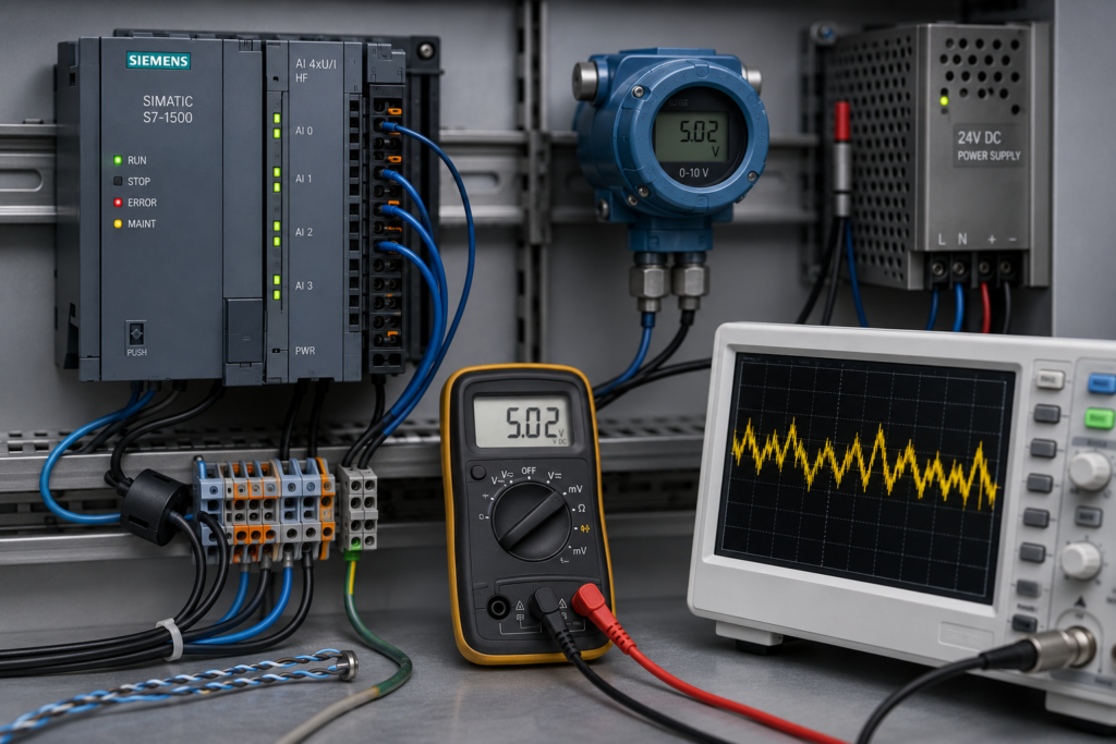
A 0–10 V analog signal should normally change smoothly as the measured pressure, position, speed or level changes.
Instead, the value jumps around.
A steady sensor may fluctuate between 5.1 and 5.6 V. The PLC raw value moves by hundreds of counts. Worse, the reading changes whenever a contactor operates, a VFD accelerates or a nearby motor starts.
Adding software filtering might make the displayed value look calmer, but it does not necessarily solve the fault. The noise may come from cable routing, grounding, a weak signal reference, the transmitter supply or even the process itself.
The right approach is to identify where the instability first appears.
Why Are 0–10 V Signals Sensitive to Noise?
A voltage signal is measured relative to a reference conductor.
If electrical noise changes either the signal voltage or its reference potential, the PLC sees a different measurement—even when the sensor output itself has not changed.
A 0.1 V disturbance equals 1% of a 0–10 V range. For a level transmitter scaled from 0 to 10 metres, that disturbance becomes a displayed change of 0.1 metres.
Common noise sources include:
- VFD output cables
- Contactors and relays
- Solenoid valves
- Braking resistors
- Large motors
- Welding equipment
- Switching power supplies
- Poor grounding
- Long signal cables
- Shared 0 V conductors
Voltage signals are therefore usually better suited to shorter, well-controlled cable runs. For long industrial field wiring, 4–20 mA is often the more robust choice.
First, Confirm That the Signal Is Actually Unstable
Monitor three values separately:
- The physical voltage at the sensor output
- The voltage at the PLC analog input
- The raw and scaled PLC values
This comparison tells you where the disturbance is entering.
Sensor Output Is Already Unstable
Investigate the sensor, its power supply or the real process measurement.
Sensor Output Is Stable but PLC Terminal Voltage Moves
The problem is probably in the cable, grounding, reference conductor or electrical environment.
PLC Terminal Voltage Is Stable but Raw Value Moves
Check the channel configuration, analog module, input diagnostics, sample settings and measurement method.
Do not judge a fast-changing signal with an ordinary multimeter alone. Its display may average brief disturbances that the PLC detects.
Step 1: Check the Analog Input Configuration
Open the analog channel properties in TIA Portal and verify that the channel is configured for the correct voltage range.
Depending on the module, possible ranges may include:
- 0–10 V
- ±10 V
- ±5 V
- ±2.5 V
- Current ranges
A 0–10 V signal connected to a channel configured incorrectly will produce misleading or unusable values.
Many Siemens voltage inputs represent 0–10 V using raw values from 0 to 27648. Values above the nominal range may represent overshoot or overflow rather than a valid measurement.
Also check that the PLC tag points to the correct input word. Monitoring the wrong channel can look like random electrical noise.
Step 2: Measure at the Sensor and PLC
Measure between the signal conductor and its actual analog common.
Take readings:
- Directly at the sensor
- At any field junction box
- At the panel terminal block
- Directly at the PLC input
Perform the measurements while the machine is operating and while the noisy value is visible.
If the voltage is stable at the sensor but unstable at the PLC, the problem occurs between those two points.
If the voltage is different at opposite ends of the cable, check:
- Cable resistance
- Loose terminals
- Damaged conductors
- Shared commons
- Ground-potential differences
- Unwanted current in the reference conductor
Step 3: Check the Signal Reference
The PLC does not measure only the positive signal wire. It measures the difference between the signal and its reference.
A loose or noisy analog common can therefore disturb several channels simultaneously.
Inspect:
- Sensor 0 V connection
- PLC analog common
- Power-supply negative terminal
- Terminal links
- Isolation boundaries
- Grounding points
- Shared return conductors
Where the sensor and PLC use separate power supplies, confirm whether their reference conductors must be connected. Do not join isolated supplies blindly; follow the sensor and analog-module wiring diagrams.
If several analog readings jump at exactly the same moment, a shared reference problem is more likely than several sensors failing together.
Step 4: Inspect Cable Routing
Follow the analog cable from the sensor to the panel.
It should not run unnecessarily beside:
- Three-phase motor cables
- VFD output conductors
- Braking-resistor cables
- Contactor power wiring
- High-current switched DC wiring
Siemens recommends separating low-voltage signal wiring from AC and rapidly switched high-energy wiring. It also recommends routing conductors as pairs so the signal and its return remain together.
Crossing a power cable at approximately 90 degrees is generally better than running parallel with it for several metres.
Moving the analog cable a short distance away from a VFD motor cable can sometimes make an immediate difference.
Step 5: Use Shielded Twisted-Pair Cable
A 0–10 V analog signal should normally use a suitable shielded twisted pair.
Twisting keeps the outgoing signal and return physically close together, helping induced noise affect both conductors more equally. Shielding helps intercept external electrical interference.
Siemens specifies shielded twisted-pair cable for its integrated S7-1200 analog voltage inputs and lists a maximum cable length of 100 metres for the referenced CPU inputs. The exact limit depends on the module.
Check whether:
- The shield is continuous
- The shield has not been used as the signal common
- The cable is damaged
- Unshielded sections are unnecessarily long
- The shield termination follows the manufacturer’s guidance
Step 6: Check Shield Grounding
Shield grounding is not as simple as “always connect one end” or “always connect both ends.”
Siemens’ current S7-1200 wiring guidance recommends grounding cable shields with a low-impedance, high-surface-area connection and describes grounding shields at both ends. Rockwell documentation for another analog input system notes that grounding at the module end may often provide sufficient immunity, while both-end grounding can improve shield performance when ground-current problems are controlled.
The correct method depends on:
- Equipment design
- Cable length
- Frequency of the interference
- Equipotential bonding
- Site grounding system
- Manufacturer instructions
A thin, long shield “pigtail” has relatively poor high-frequency performance. A proper shield clamp usually provides a better connection.
Do not use the shield as the analog signal return.
Step 7: Check the Sensor Power Supply
The sensor output may be unstable because its supply is unstable.
Measure the supply directly at the sensor while the fault occurs.
Look for voltage dips when:
- Solenoids energise
- Contactors pull in
- Motor brakes release
- Several outputs switch together
- A large DC load starts
If the analog sensor shares a 24 V supply with heavy inductive loads, disturbances may reach the transmitter through its power connection.
Possible improvements include:
- Separating sensitive instrumentation loads
- Repairing loose power connections
- Adding suitable suppression to coils
- Using an isolated DC/DC converter
- Installing a dedicated instrumentation supply
Do not add capacitors randomly across sensor outputs. They can slow the measurement, overload the output or create control instability.
Step 8: Check the Signal Source Impedance
A voltage transmitter must be capable of driving the PLC input and the connected cable.
The integrated 0–10 V inputs on the referenced Siemens S7-1200 CPU have an input impedance of at least 100 kΩ, but other modules and devices may differ.
Problems are more likely when the 0–10 V signal comes from:
- A high-value potentiometer
- A passive resistor network
- A weak electronic output
- Several inputs connected in parallel
- A long cable with significant capacitance
- An unsuitable signal converter
Check the permitted load resistance in the transmitter manual.
If several PLC, display or controller inputs share one voltage signal, their combined input resistance becomes lower. Use a proper signal splitter or isolator when necessary.
Step 9: Look for Ground Loops
A ground loop occurs when two devices connected by a signal cable also have different grounding paths.
The resulting unwanted current can flow through the signal reference or shield and disturb the measured voltage.
Clues include:
- The reading changes when another machine starts
- Noise disappears when using a battery-powered test source
- Voltage exists between the sensor and PLC reference points
- The problem appears only after equipment is bonded together
- Several channels shift by similar amounts
An isolated signal converter can separate the two sides, but do not install one before confirming that grounding is actually the cause.
Step 10: Test With a Known Voltage Source
Disconnect the field signal according to the approved procedure and connect a calibrator or stable test source directly to the PLC input.
Test several values:
- 0 V
- 2.5 V
- 5 V
- 7.5 V
- 10 V
If the PLC reading becomes stable, the module is probably healthy. Continue investigating the sensor, cable and grounding.
If the value remains unstable with a short direct test connection, check:
- Module power
- Channel configuration
- Adjacent wiring
- Module diagnostics
- Analog input hardware
Use a test source designed for analog calibration. A random bench supply may introduce its own ripple or grounding path.
Step 11: Review Noise Rejection and Smoothing
Siemens analog inputs may offer selectable noise rejection and smoothing.
Depending on the module, available rejection settings may include:
- 10 Hz
- 50 Hz
- 60 Hz
- 400 Hz
Smoothing may be available as:
- None
- Weak
- Medium
- Strong
These settings average samples and reject selected interference frequencies, but stronger filtering also slows the response. On one Siemens analog module family, strong smoothing with 10 Hz rejection can create a step response of several seconds.
Choose settings according to the process.
Strong smoothing may be acceptable for:
- Tank level
- Room temperature
- Slowly changing pressure
It may be unsuitable for:
- Fast pressure control
- Tension control
- Position feedback
- Rapid machine movement
Filtering should reduce small remaining fluctuations after the wiring is correct. It should not hide a missing analog common or a cable routed beside a VFD output.
Step 12: Determine Whether the Process Is Moving
Not every unstable analog value is electrical noise.
A real process can fluctuate because of:
- Pump pulsation
- Valve hunting
- Mechanical vibration
- Tank turbulence
- Unstable pressure regulators
- Loose position-sensor linkage
- Poor sensor mounting
- Air bubbles in impulse tubing
Compare the PLC value with an independent gauge or measuring instrument.
If the physical process changes at the same time, repairing the analog wiring will not make the measurement steady.
Fast Troubleshooting Sequence
- Compare voltage at the sensor and PLC.
- Verify the configured input range.
- Check the analog common and 0 V reference.
- Inspect cable routing near VFD and motor wiring.
- Confirm shielded twisted-pair cable is used.
- Check shield termination.
- Measure the sensor supply under operating conditions.
- Confirm the transmitter can drive the input load.
- Check for ground-potential differences.
- Test the PLC input with a calibrator.
- Review noise-rejection and smoothing settings.
- Confirm the process itself is stable.
Final Thoughts
An unstable 0–10 V signal should be traced as an electrical path:
Sensor → signal cable → reference conductor → terminal blocks → analog input → PLC filtering
Measure at both ends of the cable before changing the program. If the sensor output is stable but the PLC input is not, concentrate on wiring, shielding and grounding.
Software smoothing has its place, but use it last.
A filtered bad signal is still a bad signal. It simply looks calmer on the HMI.