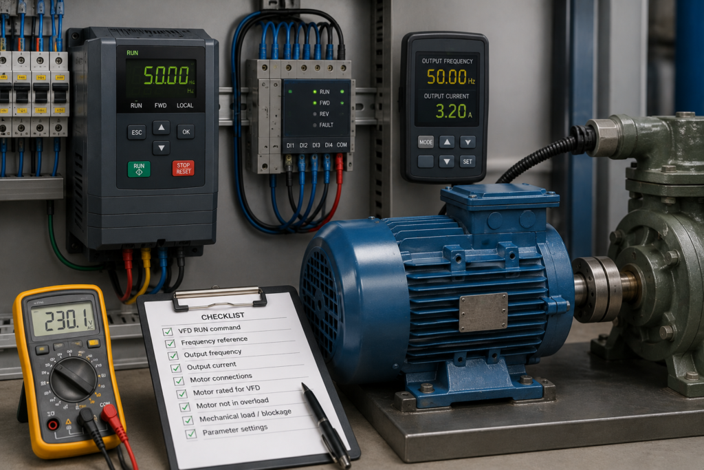
The VFD display changes from 20 Hz to 40 Hz, yet the motor appears to run at the same speed.
This can be confusing because changing frequency is the normal method a variable frequency drive uses to control an AC motor. However, the number displayed on the keypad may be a requested frequency rather than the frequency actually being sent to the motor.
The motor may also be changing speed while the driven machine is not. A slipping belt, failed coupling or gearbox problem can hide what the motor shaft is really doing.
The first step is to separate four different values:
- Requested speed or frequency
- Actual VFD output frequency
- Actual motor-shaft speed
- Speed of the driven machine
Work Safely Around the Drive
A VFD contains hazardous voltage even after its incoming supply has been switched off.
Before opening terminals, inspecting couplings or disconnecting the motor:
- Isolate and lock out the incoming supply
- Wait for the DC bus to discharge
- Verify the absence of voltage
- Secure the machine against unexpected movement
- Follow the manufacturer’s safety instructions
Do not disconnect the motor while the VFD is producing output.
Step 1: Confirm What the Displayed Frequency Represents
The keypad may display any of the following:
- Frequency setpoint
- Actual output frequency
- Motor frequency
- Calculated motor speed
- Process-controller output
- Maximum permitted frequency
- Reference from the PLC
A changing setpoint does not prove that the drive accepted or applied it.
Open the monitoring menu and compare:
- Active frequency reference
- Ramp-generator output
- Actual output frequency
- Calculated or measured speed
- Motor current
- Output voltage
- Drive status
SINAMICS drives provide separate monitoring values for requested speed and actual motor frequency. Siemens documentation, for example, identifies a dedicated value for actual motor frequency rather than treating every displayed reference as the real output.
Step 2: Measure the Real Motor Speed
Do not estimate speed only from sound.
Use:
- A handheld tachometer
- Encoder feedback
- A drive speed-monitoring value
- A marked shaft and suitable speed instrument
Run the motor at two clearly different frequency commands, such as 20 Hz and 40 Hz.
For a normal induction motor, shaft speed should change approximately in proportion to the applied frequency. The exact speed remains slightly below synchronous speed because induction motors require slip to produce torque.
If the shaft speed changes but the machine speed does not, move directly to the mechanical transmission checks.
Step 3: Check Whether the Output Frequency Actually Changes
Monitor the VFD’s real output frequency while changing the reference.
Setpoint Changes, but Output Frequency Does Not
The drive is ignoring, limiting or replacing the requested reference.
Possible causes include:
- Wrong speed-reference source
- Fixed-frequency input active
- PID controller controlling the speed
- Minimum or maximum frequency limit
- Jog mode active
- Communication reference not enabled
- Drive operating in local mode
- A speed limit from another parameter
- A safety speed function active
- Ramp generator held or frozen
Output Frequency Changes, but Shaft Speed Does Not
Possible causes include:
- Motor is stalled
- Mechanical brake remains applied
- Load is too heavy
- Coupling or gearbox is locked
- Wrong motor data
- Incorrect motor wiring
- Motor is not connected to the monitored drive
- Encoder or displayed speed feedback is wrong
Watch output current during the test. A rising frequency with high current and little shaft movement suggests that the motor is producing torque against a blocked or overloaded system.
Step 4: Verify the Active Speed-Reference Source
Most drives can receive a speed reference from several places:
- Keypad
- Analog input
- Fixed frequencies
- PLC fieldbus
- Motorised potentiometer
- PID controller
- Internal drive logic
- Pulse input
The HMI may be changing a PLC tag that is not currently selected as the active drive reference.
For example, the drive might receive its run command over PROFINET but still use analog input 1 for speed. The PLC value changes correctly, yet the drive ignores it.
Check the active command data set and setpoint source. On Siemens drives, the selected source and internal signal connections can determine which reference reaches the speed-control chain.
As a controlled test, place the drive in local mode and vary the frequency from the keypad. If the motor responds locally, the drive and motor are probably functional. Concentrate on PLC communication and reference selection.
Step 5: Check for Fixed-Speed Commands
Digital inputs can be assigned to preset or fixed frequencies.
When one of these inputs is active, it may replace the normal analog or communication reference. The displayed HMI value changes, but the motor continues running at the selected fixed speed.
Check the live digital-input status and assignments for functions such as:
- Fixed frequency bit 0
- Fixed frequency bit 1
- Jog
- Potentiometer increase
- Potentiometer decrease
- Reference selection
- Local/remote selection
A shorted wire or incorrect PLC output can keep a fixed-speed command permanently active.
Step 6: Review Minimum and Maximum Frequency
The requested frequency may be outside the permitted limits.
The drive normally restricts the reference between its configured minimum and maximum values. Siemens states that the speed setpoint is limited by both minimum and maximum frequency parameters.
For example:
- Requested frequency: 10 Hz
- Minimum frequency: 25 Hz
- Actual output: 25 Hz
Changing the request between 5 Hz and 20 Hz would then produce no change in motor speed.
The same problem appears at the upper limit. If maximum frequency is set to 40 Hz, commands of 45 Hz and 50 Hz still result in approximately 40 Hz output.
Check both positive and negative speed limits where reverse operation is permitted.
Step 7: Check the Acceleration and Deceleration Ramps
The motor may be changing speed, but so slowly that it appears fixed during a short test.
A long acceleration time can be intentional on:
- Conveyors
- Centrifuges
- Large fans
- Pumps
- High-inertia machines
Monitor the ramp-generator output.
If the setpoint jumps immediately from 20 Hz to 50 Hz but the output rises gradually, the drive is following its configured acceleration ramp.
Also check whether:
- Ramp time is unusually long
- Ramp smoothing is enabled
- Current limiting extends acceleration
- DC bus control holds the ramp
- The load prevents normal acceleration
Do not reduce acceleration time without checking motor current, mechanical stress and process requirements.
Step 8: Look for Current or Torque Limiting
A heavily loaded motor may be unable to follow the increasing frequency command.
When motor current reaches the drive limit, the VFD may reduce or hold the frequency to avoid an overcurrent trip. Siemens documentation describes current limiting that becomes active when actual output current exceeds the configured current limit.
Monitor:
- Output current
- Current-limit-active status
- Torque limit
- Speed-controller output
- Actual frequency
- Acceleration state
Possible causes include:
- Jammed machine
- Mechanical brake not releasing
- Motor too small
- Incorrect motor connection
- Supply voltage too low
- Current limit set too low
- Motor data entered incorrectly
Do not simply increase the limit. Confirm that the motor and machine can safely handle more torque.
Step 9: Check the Mechanical Brake
Motors used on hoists, lifts, geared drives and positioning systems may have a spring-applied brake.
The VFD can increase its output frequency while the brake remains partially or fully applied.
Check:
- Brake-coil voltage
- Brake contactor
- Brake-release timing
- Brake rectifier
- Mechanical clearance
- Brake feedback
- Drive brake-control parameters
A partially released brake may allow the motor to turn at low load but prevent it from accelerating normally.
Repeated operation in this condition can overheat both the motor and brake.
Step 10: Inspect Belts, Couplings and Gearboxes
If motor-shaft speed changes correctly but machine speed does not, the fault is mechanical.
Look for:
- Loose or slipping belt
- Worn pulley
- Broken coupling insert
- Loose shaft key
- Sheared pin
- Failed clutch
- Damaged gearbox
- Variable-speed pulley stuck in one position
- Conveyor roller slipping on its shaft
Mark both sides of a coupling and observe whether they remain aligned while running under load.
A failed coupling can leave the motor spinning normally while the machine moves slowly—or not at all.
Step 11: Check for Bypass Operation
Some VFD systems include a bypass contactor that connects the motor directly to mains power.
When the motor is running in bypass, changing the VFD frequency has no effect because the motor is no longer being supplied by the drive.
Check:
- VFD contactor status
- Bypass contactor status
- Selector-switch position
- Automatic transfer logic
- Auxiliary feedback contacts
- Output voltage at the motor
In bypass mode, the motor normally runs close to its fixed mains-frequency speed.
Never operate the VFD output and bypass supply onto the motor simultaneously unless the system was specifically designed for such transfer.
Step 12: Verify the Motor Nameplate Data
Incorrect motor data can produce poor speed estimation and weak speed control.
Check:
- Rated voltage
- Rated current
- Rated frequency
- Rated speed
- Rated power
- Power factor
- Number of poles
- Star or delta connection
Perform the manufacturer’s motor-identification or autotuning procedure after entering the correct values.
In open-loop V/f control, displayed “actual speed” may be a calculated value rather than a direct measurement. Siemens documentation notes that calculated speed can be derived from output frequency and estimated slip when no encoder is used.
If accurate speed confirmation is required, use real encoder feedback or an external tachometer.
Step 13: Consider Normal Motor Slip
A loaded induction motor does not run at exactly synchronous speed.
For example, a four-pole motor supplied at 50 Hz has a synchronous speed of 1,500 rpm, but its nameplate speed may be around 1,440–1,480 rpm.
As load increases, slip increases and shaft speed falls slightly. Most standard induction motors run at roughly 96% to 99% of synchronous speed at full load.
A small difference is normal.
A motor remaining at nearly the same speed while commanded frequency changes substantially is not normal and needs further investigation.
Fast Troubleshooting Sequence
- Identify whether the display shows setpoint or actual frequency.
- Measure the real motor-shaft speed.
- Compare setpoint, ramp output and actual output frequency.
- Verify the active speed-reference source.
- Check fixed-speed and jog inputs.
- Review minimum and maximum frequency limits.
- Check acceleration and deceleration ramps.
- Monitor current and torque limiting.
- Verify brake release.
- Inspect belts, couplings and gearbox.
- Confirm the motor is not running in bypass.
- Verify motor data and perform autotuning.
Final Thoughts
A changing number on the VFD display does not prove that the motor receives a changing frequency.
Begin by comparing the requested reference with the actual drive output. Then measure the motor shaft directly.
If the output frequency does not follow the request, investigate reference selection, fixed speeds, limits and control modes.
If the frequency changes but the shaft does not, inspect current limiting, the brake, mechanical load and motor configuration.
And if the motor speed changes but the machine does not, stop looking inside the drive. The fault is probably somewhere between the shaft and the driven equipment.