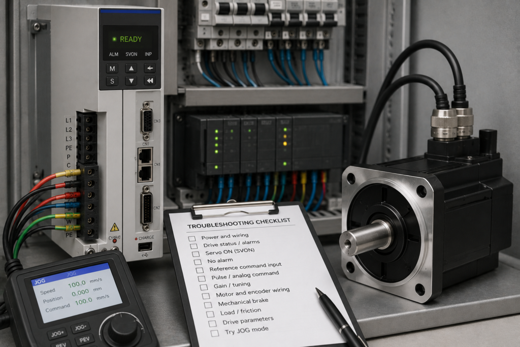
The servo drive display says Ready. Communication with the PLC is healthy, and no obvious fault is active. You issue a positioning or jog command, but the motor does not move.
“Ready” sounds as though the servo should operate immediately. In practice, it often means only that the drive has completed startup and is available to receive the remaining enable signals.
The drive may still be waiting for Servo ON, Safe Torque Off may be active, a travel limit may be blocking the selected direction, or the motion controller may not be sending a valid command.
The quickest troubleshooting method is to compare the drive state, motion command, torque output and encoder feedback separately.
Work Safely Around Servo Systems
Servo motors can accelerate unexpectedly and produce high torque almost instantly.
Before enabling or testing an axis:
- Keep personnel away from the mechanism
- Support vertical loads
- Confirm emergency-stop operation
- Secure loose tools and machine parts
- Check software and hardware travel limits
- Use a low jog speed for initial testing
- Follow the machine’s approved commissioning procedure
Never bypass STO, limit switches or mechanical brakes merely to make the axis move.
“Ready” Does Not Always Mean “Servo Enabled”
Servo drives normally pass through several operating states.
These may include:
- Not ready
- Ready to switch on
- Ready for operation
- Servo ON
- Operation enabled
- Motion active
- Faulted
- Switching-on inhibited
A drive can report that it is ready for Servo ON while its power stage is still disabled. Siemens V90 diagnostics, for example, separate the ready for servo on state from the condition in which the servo has actually been switched on.
Check the exact status bits instead of relying only on one green LED or the word “Ready.”
Step 1: Confirm Servo ON or Operation Enable
Look for a status such as:
- Servo ON
- Operation enabled
- Power enabled
- Axis enabled
- Drive active
- Torque enabled
When operation is truly enabled, the drive energises the motor and begins controlling its position, speed or torque.
A disabled servo motor may rotate freely by hand when no brake is fitted. Once enabled, it normally resists movement because the control loop is holding its position.
If the drive remains only “ready to switch on,” check:
- Servo-enable input
- PLC enable command
- Control-word bits
- Emergency-stop reset
- Drive-enable sequence
- Communication control authority
- Active inhibit conditions
Siemens control examples require several releases in the control word before the final switch-on command enables motion. A single run or enable bit may therefore be insufficient.
Step 2: Read Faults, Warnings and Inhibit Status
Do not assume that no red fault LED means nothing is blocking motion.
Open the diagnostic screen and check for:
- Switching-on inhibited
- STO active
- Limit switch active
- Axis not referenced
- Communication control missing
- Brake feedback missing
- Motor identification incomplete
- Encoder warning
- Following error
- Quick stop active
- Operation enable missing
Some drive states are warnings or inhibits rather than trip faults. The drive remains online and “ready,” but it refuses to produce torque.
Review the complete status word, diagnostic buffer and active warning list.
Step 3: Check Safe Torque Off
Safe Torque Off prevents the drive from producing motor torque while leaving its control electronics powered.
This means:
- The display remains active
- Network communication continues
- The PLC may see the drive
- Parameters can be monitored
- The motor cannot produce commanded torque
Check:
- Both STO channels
- Safety relay outputs
- Emergency-stop circuit
- Guard switches
- Safety PLC status
- PROFIsafe communication
- STO terminal voltage
- Safety acknowledgement
The Siemens V90 status information includes a separate indication showing whether STO is active because the required enable signal is missing.
Do not bridge STO terminals as a troubleshooting shortcut. Find why the safety permission is absent.
Step 4: Inspect the PLC Control Word
When the drive is controlled over PROFINET, EtherCAT, EtherNet/IP or another network, the PLC usually sends a control word containing several separate commands.
Depending on the system, these may include:
- Switch on
- Enable voltage
- Quick-stop release
- Enable operation
- Fault reset
- Control by PLC
- Motion enable
Compare the control word sent by the PLC with the drive’s returned status word.
A common problem is that the drive is ready, but one stop-related bit remains false. The PLC may have issued Servo ON while still commanding quick stop or coast stop.
Also confirm that the drive accepts control from the PLC. It may currently be assigned to:
- Local commissioning software
- Keypad control
- Terminal control
- Another controller
- A different telegram or command source
Step 5: Confirm That a Real Motion Command Exists
An enabled servo does not move until it receives a valid speed, position or torque command.
Monitor:
- Target position
- Actual position
- Target speed
- Actual speed
- Motion-command active bit
- Commanded torque
- Motion-block busy status
- Motion-block error code
The requested position may equal the current position. In that case, the drive is working correctly and has nowhere to move.
Other command-side causes include:
- Jog speed set to zero
- Relative distance set to zero
- Speed override at 0%
- Motion command not receiving a rising edge
- Motion block not being called
- Wrong axis selected
- Command immediately aborted
- Position units scaled incorrectly
- Pulse command not reaching the drive
In position-control mode, the controller must provide a target position or command pulses. The servo drive then uses motor and encoder feedback to reach that target.
Step 6: Check the Selected Control Mode
Confirm whether the drive is configured for:
- Position control
- Speed control
- Torque control
- Internal positioning
- Pulse-train positioning
- Network motion control
A speed reference will not necessarily move a drive configured to wait for position commands. Likewise, a positioning block cannot work correctly if the drive is operating in torque mode.
Check that the PLC technology object, telegram and drive mode agree.
After replacing or factory-resetting a drive, do not assume the default operating mode matches the original machine.
Step 7: Check Hardware and Software Limits
A triggered travel limit can block movement in one direction.
Check:
- Positive hardware limit
- Negative hardware limit
- Positive software limit
- Negative software limit
- Emergency limit
- Travel-range configuration
- Input polarity
- Limit-switch wiring
Omron describes forward and reverse drive-prohibit inputs as functions that stop the servo from rotating farther in the prohibited direction when the corresponding input becomes inactive.
If the axis moves in one direction but not the other, limit logic should be one of the first checks.
Verify that normally closed limit-switch circuits are wired and configured with the correct polarity. A broken wire can look like a permanently active limit.
Step 8: Confirm That the Axis Is Referenced
An incremental encoder does not automatically know the machine’s absolute position after power-up.
Some positioning systems therefore prevent normal absolute moves until a homing or referencing procedure has been completed. Omron notes that an incremental-encoder servo needs an origin search after startup to establish its position.
Check:
- Referenced or homed status
- Homing-required bit
- Absolute encoder validity
- Encoder battery alarm
- Home-switch input
- Homing mode
- Reference completion status
A manual jog may still work while normal positioning commands are rejected.
Step 9: Check the Motor Holding Brake
Many servo motors contain a spring-applied holding brake.
The drive can enable correctly and produce torque while the brake remains mechanically applied.
Inspect:
- Brake power supply
- Brake relay or contactor
- Brake output from the drive
- Brake rectifier
- Brake-release delay
- Brake feedback
- Brake cable
- Mechanical brake condition
Siemens V90 systems require the motor holding brake to be configured when a brake-equipped motor is used.
Measure the brake voltage during the motion command. A failed brake coil, broken cable or incorrect control sequence can leave the shaft locked.
A motor holding brake is not normally intended to stop repeated high-speed movement. It mainly holds the axis after motion has stopped.
Step 10: Review Torque Limits
A torque limit set too low may allow the servo to enable but prevent it from moving the load.
Monitor:
- Torque reference
- Actual torque
- Positive torque limit
- Negative torque limit
- Current limit
- Torque-limit-active bit
Torque limiting is intentionally used to protect motors and mechanical systems from excessive force. If configured near zero, however, the motor may not overcome friction, gravity or the holding brake.
Do not simply raise the limit to maximum. Check the machine’s safe allowable force first.
Step 11: Inspect the Motor and Encoder Connections
The drive depends on correct motor-power and encoder feedback connections.
Check:
- Motor cable fully connected
- Encoder cable fully connected
- Connector locking mechanisms
- Correct motor selected
- Correct encoder type
- Damaged connector pins
- Cable shielding
- Phase and feedback cable compatibility
- DRIVE-CLiQ or feedback communication status
An encoder problem normally produces a fault, but intermittent or incorrectly scaled feedback can also prevent controlled movement.
Monitor actual position while turning the shaft manually with the drive safely disabled. The displayed position should change smoothly and in the expected direction.
Do not disconnect an encoder or motor cable while the drive is powered.
Step 12: Check for a Mechanical Jam
If the drive is enabled and commanding torque but the actual position does not change, inspect the machine.
Possible causes include:
- Brake stuck on
- Gearbox seized
- Linear guide jammed
- Coupling damaged
- Axis against a hard stop
- Product trapped in the mechanism
- Excessive belt tension
- Vertical load unsupported
- Motor incorrectly sized
Compare commanded torque with actual movement.
High torque and zero speed point toward a mechanical obstruction or applied brake. Near-zero torque with no movement points back toward enable, command or torque-limit conditions.
Step 13: Test With the Commissioning Jog Function
Where the machine can be made safe, use the drive’s commissioning software or control panel to jog the motor at low speed.
First disconnect the mechanical load where the approved procedure allows it.
Motor Moves in Commissioning Mode
The drive, motor and feedback system are probably functional. Concentrate on PLC commands, telegrams, technology-object configuration and motion logic.
Motor Still Does Not Move
Focus on:
- STO
- Servo enable
- Brake release
- Motor and encoder wiring
- Drive commissioning
- Mechanical binding
- Incorrect motor selection
Maintain immediate access to the stop function during testing.
Fast Troubleshooting Sequence
- Confirm the drive is operation-enabled, not merely ready.
- Read every active fault, warning and inhibit.
- Check STO and safety permissions.
- Compare the PLC control word with the drive status word.
- Confirm that a non-zero motion command exists.
- Verify the selected position, speed or torque mode.
- Check hardware and software travel limits.
- Confirm the axis is referenced where required.
- Verify that the holding brake releases.
- Review torque and current limits.
- Inspect motor and encoder cables.
- Check the mechanism for a jam.
- Test a low-speed commissioning jog safely.
Final Thoughts
A servo drive showing Ready has not necessarily been given permission to produce torque or execute movement.
Begin by confirming the true drive state. Then follow the command chain:
Safety permission → Servo ON → Operation enabled → Motion command → Torque output → Encoder movement
The first missing condition identifies the section that needs attention.
Do not replace the drive simply because the motor remains still. In many cases, the servo system is correctly refusing movement because one enable, limit, brake or motion condition has not been satisfied.