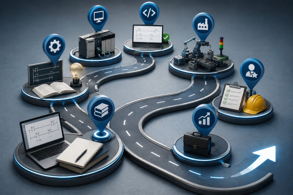
Becoming a PLC programmer is possible without previous automation experience.
It is not, however, a weekend project.
Watching a few ladder-logic videos may teach you how to energise an output. That is useful, but real industrial automation involves much more: electrical drawings, sensors, contactors, motor starters, variable-frequency drives, industrial networks, fault-finding and—most importantly—machinery that can hurt people when programmed badly.
A realistic goal is not to “master PLC programming” as quickly as possible. It is to become useful enough that a company can trust you around an industrial control system.
For someone starting completely from zero, that may take 12 to 24 months of consistent learning and practice. Someone who already works as an electrician, maintenance technician or machine builder may be ready for an entry-level automation role considerably sooner.
What Does a PLC Programmer Actually Do?
PLC programming is only one part of the job.
Depending on the company, a PLC programmer or automation engineer may need to:
- Read electrical schematics
- Select and configure PLC hardware
- Write ladder logic and structured text
- Configure remote I/O
- Program HMI screens
- Set up VFDs and servo drives
- Connect sensors and actuators
- Configure industrial Ethernet networks
- Commission machines
- Diagnose electrical and software faults
- Modify existing production equipment
- Document changes and create backups
Quite a lot, in other words.
This is why someone who understands only ladder logic may struggle during a real commissioning job. The program might be correct while the sensor is wired incorrectly, the drive is using the wrong control source or a network device has been assigned the wrong address.
A useful PLC programmer must understand the complete system—not merely the code.
Stage 1: Learn Basic Electricity First
Suggested time: one to two months
You do not need to become a qualified electrician before learning PLCs, but you do need to understand the equipment connected to them.
Begin with:
- Voltage, current and resistance
- AC and DC systems
- Series and parallel circuits
- Normally open and normally closed contacts
- Relays and contactors
- Motor starters and overload relays
- Fuses and circuit breakers
- PNP and NPN sensors
- Sourcing and sinking inputs
- 24 V DC control circuits
- Basic three-phase motor operation
- Safe isolation and lockout procedures
Learn how to use a multimeter safely. Understand the difference between measuring voltage, resistance and current. Know why resistance testing must not be performed on an energised circuit.
You should also be able to follow a simple control circuit containing:
Control supply
→ Stop button
→ Start button
→ Overload contact
→ Contactor coil
This may seem unrelated to programming. It is not.
PLC logic is largely a software representation of the same decisions that were once implemented using relays and hardwired control circuits.
Stage 2: Learn How a PLC Works
Suggested time: one to two months
Before choosing Siemens, Allen-Bradley or another platform, learn the principles shared by almost every PLC.
Start with the scan cycle:
- Read the physical inputs.
- execute the program.
- update the outputs.
- perform communications and internal tasks.
- Repeat.
Then learn the core instructions:
- Examine if closed and examine if open
- Output energise
- Latching and unlatching
- On-delay and off-delay timers
- Counters
- Comparisons
- Move and copy instructions
- Mathematical instructions
- One-shot instructions
- Basic sequencers
- Function blocks
- Program routines and subroutines
Ladder Diagram, Function Block Diagram and Structured Text are part of the IEC 61131-3 family of PLC programming languages. Learn ladder first, but do not treat it as the only language worth knowing. Structured Text becomes particularly useful for calculations, arrays, loops, recipes and data processing.
At this stage, practise questions such as:
- What happens during the first PLC scan?
- What happens when two instructions write to the same output?
- Why does a timer reset?
- What is the difference between a physical input and an internal Boolean tag?
- What happens when an input changes halfway through a scan?
- Why can a latched output remain on after the original condition disappears?
These small details separate functioning logic from mysterious logic.
Stage 3: Start With Simulation
You do not need to buy an industrial PLC immediately.
In fact, buying hardware too early can waste money. A controller sitting on your desk is not particularly educational when you still do not know what project to build with it.
Several legitimate tools allow beginners to start without expensive hardware.
CODESYS
The CODESYS Development System can be downloaded free of charge. Its installation includes a demonstration SoftPLC, allowing you to create and test IEC 61131-3 programs on a computer before purchasing physical equipment.
CODESYS is useful for learning:
- Variables and data types
- Ladder logic
- Structured Text
- Function blocks
- Program organisation
- Visualisation
- Basic simulation and debugging
It will not make you an expert in Siemens or Allen-Bradley software, but the programming principles transfer.
Connected Components Workbench
Rockwell Automation offers a free Standard Edition of Connected Components Workbench. It supports Micro800 programming and includes access to Micro800 simulation features, although some simulator functionality may be limited compared with the paid edition.
CCW is a reasonable starting point for Rockwell-style hardware, especially when you cannot yet access Studio 5000.
Be aware, though, that Micro800 programming in CCW is not identical to programming CompactLogix or ControlLogix in Studio 5000. The basic logic transfers, but the engineering workflow, project structure and controller capabilities differ.
Siemens learning resources
Siemens Automation Cooperates with Education provides more than 100 downloadable learning and training documents, including material covering PLC programming, TIA Portal, networking, HMI systems and automation projects. Siemens also offers digital modules intended for independent study.
Students and trainees can also access learning material and trial-software options through Siemens SCE resources.
The important thing is not which free simulator you choose first.
Choose one. Build things.
Stage 4: Complete Small PLC Projects
Suggested time: two to three months
Do not spend six months watching tutorials without creating anything yourself.
Tutorials make programming look easy because someone else has already decided how the program should work. Your real learning begins when you must convert a vague machine description into working logic.
Start with small projects.
Project 1: Motor Start-Stop Circuit
Create a program containing:
- Start button
- Stop button
- Motor output
- Seal-in circuit
- Overload input
- Running indicator
- Fault indicator
- Reset button
Then add complications:
- The motor may not restart automatically after power restoration.
- The overload must be reset before starting.
- A start command must be ignored while the fault is active.
- The running lamp should follow feedback, not merely the output command.
A basic motor rung is easy. A believable motor-control routine requires more thought.
Project 2: Tank Filling System
Create a tank with:
- Low-level sensor
- High-level sensor
- Inlet valve
- Outlet valve
- Pump
- Automatic and manual modes
- High-level alarm
- Sensor-disagreement alarm
Then answer awkward questions.
What happens when both level sensors are active? What happens when neither sensor changes after the valve opens? What happens after power is restored halfway through the sequence?
That is where programming becomes engineering.
Project 3: Conveyor With Jam Detection
Include:
- Start and stop controls
- Motor starter
- Entry and exit sensors
- Product-travel timer
- Jam alarm
- Manual reset
- Downstream permissive
- Running feedback
The conveyor should stop when a product enters but does not reach the exit sensor within the permitted time.
Then simulate a failed sensor, stopped downstream conveyor and motor overload.
Project 4: Traffic or Machine Sequence
Build a sequence using:
- Defined operating states
- Transition conditions
- Timers
- Fault recovery
- Manual mode
- Automatic mode
- Cycle-complete counter
Avoid controlling the entire sequence with a pile of overlapping timer bits. Learn to create an explicit state number or sequence structure.
It is less flashy, but much easier to troubleshoot.
Stage 5: Choose One Major Platform
Suggested time: three to six months
Once you understand PLC fundamentals, choose the platform used by employers you are likely to approach.
Do not try to master Siemens, Rockwell, Mitsubishi, Omron, Beckhoff, Schneider and CODESYS simultaneously. You will become slightly familiar with everything and employable at nothing.
Search local job listings and note which systems appear most often.
Then choose one primary route.
Siemens route
Focus on:
- TIA Portal
- S7-1200 and S7-1500
- Hardware configuration
- Ladder and FBD programming
- Data blocks
- Function blocks and functions
- Watch tables
- Online diagnostics
- PROFINET
- WinCC HMI basics
- Siemens drive integration
Siemens SCE provides structured TIA Portal learning documents and project material that can support both classroom and self-directed study.
Rockwell route
Focus on:
- Studio 5000 Logix Designer
- CompactLogix and ControlLogix
- Controller-scoped and program-scoped tags
- Routines and programs
- User-defined data types
- Add-On Instructions
- EtherNet/IP
- FactoryTalk View
- PowerFlex drives
- Online editing and fault diagnostics
Studio 5000 access is often easier through an employer, training centre or educational institution because the professional software and hardware can be expensive for an individual learner.
You can still begin with CCW and Micro800 concepts, but eventually you need experience with real Logix projects when targeting CompactLogix or ControlLogix positions.
Stage 6: Learn HMI Programming
A PLC program without an operator interface is only half a modern machine.
Learn how to create:
- Start and stop controls
- Status indicators
- Alarm screens
- Setpoint entry
- Manual-control screens
- Trend displays
- Recipe selection
- Maintenance diagnostics
- User access levels
Do not build screens that merely look attractive.
A good industrial HMI should help the operator understand:
- What the machine is doing
- Why it stopped
- What condition is missing
- What action is permitted
- What action is unsafe
An alarm saying Machine Fault is nearly useless.
An alarm saying Conveyor 2 failed to start: motor feedback missing after three seconds gives maintenance somewhere to begin.
Stage 7: Learn Industrial Communications
You do not need to become a network engineer, but modern PLC programmers cannot avoid networking.
Learn:
- IPv4 addressing
- Subnet masks
- Default gateways
- Ethernet switches
- Duplicate IP problems
- Device names
- Basic managed-switch concepts
- EtherNet/IP
- PROFINET
- Modbus TCP
- Modbus RTU
- RS-485 wiring
- Remote I/O
- Produced and consumed data
- Basic OPC UA concepts
You should be able to diagnose a simple communication problem systematically.
Can the device be pinged? Does it have the correct address? Is the PLC configured for the installed hardware? Is the correct device name assigned? Are the Ethernet link lights active? Does the switch show errors?
“No communication” is a symptom, not a diagnosis.
Stage 8: Learn Drives and Motion Basics
Many PLC jobs involve motors.
At minimum, learn how a PLC communicates with a VFD and how to handle:
- Run commands
- Direction commands
- Speed references
- Ready status
- Running status
- Fault status
- Fault reset
- Motor current
- Drive frequency
- Local versus remote control
- Network versus terminal control
You should also understand common drive faults such as:
- Overcurrent
- Overvoltage during deceleration
- Undervoltage
- Motor overload
- Ground fault
- Communication timeout
Servo systems and coordinated motion can come later. Do not begin with twelve-axis robotic motion when a basic conveyor still refuses to stop correctly.
Stage 9: Learn Troubleshooting, Not Just Programming
This is where many beginners become stuck.
They can create a program from scratch but cannot understand a machine written by someone else.
In industry, you will spend plenty of time working with programs you did not create.
Practise how to:
- Go online safely
- Find the controlling output
- Cross-reference a tag
- Trace backwards through interlocks
- Compare input LEDs with PLC input tags
- Read controller diagnostics
- Identify a missing communication connection
- Distinguish program faults from wiring faults
- Upload before making changes
- Create and verify backups
- Document modifications
Suppose a valve will not open.
Do not immediately change the PLC program.
Check:
- Is the PLC commanding the output?
- Is the output module energised?
- Is field voltage present?
- Is the wire intact?
- Does an interposing relay operate?
- Is the solenoid coil healthy?
- Is air or hydraulic pressure available?
- Is the valve mechanically stuck?
Good automation technicians move comfortably between software, electricity and machinery.
Stage 10: Build a Portfolio That Looks Industrial
Suggested time: two to four months
A portfolio should demonstrate how you think, not merely show screenshots of ladder logic.
For each project, include:
- A short machine description
- I/O list
- Sequence description
- Electrical or control diagram
- PLC program
- HMI screens
- Alarm list
- Test plan
- Fault scenarios
- Short demonstration video
- Explanation of safety assumptions
Create three or four finished projects rather than twenty abandoned experiments.
A good portfolio project might be:
Automated Mixing Tank
Inputs:
- Low-level switch
- High-level switch
- Temperature transmitter
- Emergency-stop status
- Motor feedback
Outputs:
- Fill valve
- Drain valve
- Mixer motor
- Heater command
- Alarm beacon
Functions:
- Manual and automatic modes
- Recipe setpoints
- Filling sequence
- Mixing timer
- Temperature control
- Drain sequence
- Sensor fault detection
- Motor feedback alarm
- HMI alarm history
- Cycle counter
Demonstrate both normal operation and faults.
Show what happens when the high-level sensor fails, the mixer feedback disappears or the temperature exceeds the permitted limit.
That is far more convincing than a screenshot of a start-stop rung.
Stage 11: Get Real Hardware Experience
Simulation is excellent for learning logic.
It cannot fully teach you:
- Loose terminals
- Wiring mistakes
- Electrical noise
- Bad commons
- Damaged sensors
- Incorrect network settings
- Failing relays
- Motors drawing excessive current
- Devices that behave differently from the manual
Eventually, work with real hardware.
A basic learning panel might contain:
- Small PLC
- 24 V DC power supply
- Push buttons
- Selector switches
- Indicator lamps
- Relay
- Proximity sensor
- Small HMI
- Ethernet switch
- Terminal blocks
- Fuses or suitable circuit protection
Keep the system at safe extra-low voltage where possible. There is no need to introduce mains voltage merely to prove that a PLC can switch an output.
Real industrial experience is even better.
Look for opportunities to shadow:
- Maintenance electricians
- Controls engineers
- Commissioning technicians
- Machine builders
- System integrators
- Field-service engineers
Watching an experienced technician diagnose one stubborn machine can teach more than another week of perfectly organised tutorials.
Stage 12: Apply for the Right First Job
Your first automation job may not be called PLC Programmer.
Search for roles such as:
- Junior automation engineer
- Controls technician
- Maintenance technician
- Electrical maintenance technician
- Junior controls engineer
- Commissioning technician
- Field-service technician
- Industrial electrician
- Machine builder
- Control-panel technician
- PLC technician
A maintenance role can be an excellent route into programming.
You may begin by checking sensors, replacing contactors and diagnosing motor circuits. Over time, you gain access to PLC diagnostics, minor logic changes, HMI modifications and commissioning work.
That progression is normal.
Many employers will trust a beginner to monitor a program before they trust them to rewrite it. Fair enough, really.
A Realistic Timeline
Assuming roughly five to ten focused hours per week:
Months 1–2
Learn basic electricity, relays, control circuits, sensors and safe measurement.
Months 3–4
Learn the PLC scan cycle, ladder logic, timers, counters, comparisons and data types.
Months 5–7
Build simulated projects and begin Structured Text.
Months 8–10
Choose Siemens, Rockwell or another locally relevant platform.
Months 11–14
Learn HMI programming, networking, drives and online diagnostics.
Months 15–18
Build a portfolio, work with hardware and begin applying for entry-level positions.
This is only an estimate.
Someone already employed in industrial maintenance might compress this path into six to twelve months. A complete beginner studying occasionally may need two years or more.
Consistency matters more than speed.
Do You Need a Degree?
A degree in electrical engineering, automation, mechatronics or computer engineering can help, especially when applying for engineering positions.
It is not the only route.
For technician, service and junior controls roles, practical ability can carry considerable weight. Employers need people who can read drawings, troubleshoot equipment, communicate clearly and avoid making reckless changes to production machinery.
Certifications and courses can strengthen your application, but they should support practical competence rather than replace it.
A certificate saying you completed a PLC course is useful.
A portfolio showing that you designed, programmed, tested and documented a complete machine sequence is better.
Having both is better still.
Common Beginner Mistakes
Learning only ladder logic
PLC programming also involves hardware configuration, data handling, networking, HMI systems and troubleshooting.
Switching platforms constantly
Pick one main platform long enough to become comfortable with it.
Buying expensive hardware too early
Start with simulation. Purchase equipment after you understand exactly what you need.
Copying tutorial projects without modifying them
After completing a tutorial, close it and rebuild the project from memory. Then add faults and new requirements.
Ignoring electrical knowledge
The PLC cannot detect a sensor whose 24 V supply is missing unless the system was designed to provide that diagnostic information.
Changing logic before understanding the machine
Observe first. Diagnose second. Edit last.
Learning only how to create new programs
Practise reading unfamiliar code. Maintenance and commissioning frequently involve existing projects.
Ignoring documentation
Backups, comments, alarm descriptions and change records are part of professional programming.
What “Job Ready” Actually Looks Like
You do not need to know everything.
You are probably ready to pursue an entry-level role when you can:
- Read a basic industrial schematic
- Create a PLC project and configure hardware
- Program a motor or valve sequence
- Use timers, counters and comparisons correctly
- Understand basic data types
- Build simple HMI screens
- Configure a basic Ethernet connection
- Diagnose a missing input or output
- Follow existing ladder logic
- Explain upload versus download
- Create a backup before editing
- Describe your projects clearly
- Recognise when you should stop and ask for help
That final skill is underrated.
Industrial automation punishes confident guessing.
Final Thoughts
The realistic route into PLC programming is not:
Watch course
→ Memorise ladder logic
→ Become automation engineer
It looks more like this:
Learn electricity
→ Understand control circuits
→ Learn PLC fundamentals
→ Build simulated machines
→ Choose one platform
→ Learn HMI, drives and networks
→ Troubleshoot real hardware
→ Build a portfolio
→ Enter through a junior or maintenance role
→ Keep learning
PLC programming is a good career for people who enjoy a mixture of coding, electricity, machinery and problem-solving.
Some days you will write neat, organised logic.
Other days you will spend three hours chasing a loose 0 V terminal hidden inside a junction box.
Both are part of the job.