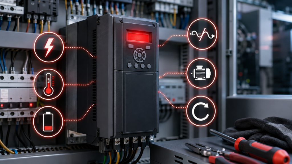
A Danfoss VLT drive stops and displays:
Alarm 13or:
Trip Lock
Alarm 14
Pressing Reset may clear the display, but that does not mean the fault has been repaired. If the motor is mechanically jammed, the DC bus is being pushed too high during deceleration or the motor cable has failed to earth, the alarm will return as soon as the drive operates again.
The first step is to record the complete alarm number and determine when it happened:
- During power-up
- Immediately after the start command
- During acceleration
- At constant speed
- During deceleration
- After communication was lost
- After parameters or hardware were changed
This guide covers common alarm numbers used across modern Danfoss FC-series drives, including the VLT AutomationDrive FC 301/302, HVAC Drive FC 102 and AQUA Drive FC 202. Older VLT products and the VLT Micro Drive FC 51 may use different alarm lists or reset procedures, so always check the manual for the exact type code and software version.
Safety warning: Danfoss drives contain DC-link capacitors that can remain charged after mains power is disconnected. Follow lockout/tagout procedures, disconnect all AC, DC-link, UPS and shared-bus supplies, wait the discharge time shown on the drive nameplate or manual, and verify the remaining voltage with a suitable meter before touching wiring. Depending on the model and power size, the required waiting time can be 20 minutes or considerably longer.
Quick Danfoss VLT Alarm-Code Chart
| Code | Meaning | Common area to inspect |
|---|---|---|
| 1 | 10 V supply low | Potentiometer or terminal 50 wiring |
| 2 | Live-zero error | Missing 4–20 mA or voltage reference |
| 4 | Mains phase loss | Input fuses, contactor, supply imbalance |
| 7 | DC overvoltage | Regeneration, short deceleration, high mains |
| 8 | DC undervoltage | Low supply, phase loss, soft-charge circuit |
| 9 | Inverter overload | Drive overloaded for too long |
| 10 | Motor ETR overtemperature | Motor overload, cooling or incorrect data |
| 11 | Motor thermistor overtemperature | Hot motor or thermistor circuit |
| 12 | Torque limit | Excessive load or restrictive torque setting |
| 13 | Overcurrent | Jam, rapid acceleration or motor fault |
| 14 | Earth fault | Motor cable or winding leaking to earth |
| 16 | Short circuit | Phase-to-phase motor or cable fault |
| 17 | Control-word timeout | PLC, fieldbus or serial communication loss |
| 29 | Heat-sink overtemperature | Fan, filters, airflow or ambient temperature |
| 30 | Motor phase U missing | Open U-phase motor circuit |
| 31 | Motor phase V missing | Open V-phase motor circuit |
| 32 | Motor phase W missing | Open W-phase motor circuit |
| 38 | Internal fault | Internal subcode, option or electronic fault |
| 50–58 | AMA failure | Motor data or identification problem |
| 59 | Current limit | Current has reached parameter 4-18 |
| 60 | External interlock | External machine condition is active |
| 80 | Drive initialized | Parameters restored to defaults |
These descriptions are shared by several modern VLT FC-series products, but the available alarms, configurable reactions and reset methods vary by drive family, options and software version.
Warning, Alarm, Trip and Trip Lock
These terms are not interchangeable.
Warning
A warning indicates an abnormal condition, but the drive may continue operating.
The warning normally disappears automatically when the condition is removed.
Alarm and trip
An alarm usually causes the drive to trip. Output to the motor is interrupted, and the motor normally coasts to a stop.
After the cause is corrected, an ordinary trip can generally be reset using:
- The Reset or Off/Reset key on the LCP
- A programmed digital input
- A fieldbus or serial command
- Automatic reset, when deliberately configured
Trip lock
A trip lock is used for conditions that require additional protection.
The drive must be disconnected from its supply before the lock can be removed. Correct the fault, follow the required capacitor-discharge procedure, restore power and then reset the drive.
Never treat a trip lock as an invitation to switch the disconnect off and immediately back on.
Check the Alarm Log Before Resetting
The alarm displayed on the LCP may not be the first event.
For example, an input phase problem could produce a low-DC-bus warning followed by an undervoltage trip. Resetting immediately removes valuable evidence.
On many FC-series drives, alarm information is available through parameter group 15-3*:
15-30  Alarm Log: Error Code
15-31  Alarm Log: Value
15-32  Alarm Log: Time
15-33  Alarm Log: Date and Time
Availability depends on the drive and software version. Record the code, stored value and operating conditions before changing parameters or cycling power.
Useful information to record includes:
Drive type code:
Software version:
Alarm number:
Trip or trip lock:
Output frequency:
Motor current:
DC-link voltage:
Reference value:
Motor thermal load:
Drive thermal load:
Operating stage:
Recent changes:
Warning/Alarm 1: 10 V Supply Low
The control-card voltage from terminal 50 has fallen below the expected level.
Terminal 50 is commonly used as a 10 V reference for a potentiometer or another low-power control circuit. Excessive load, incorrect potentiometer resistance or a short in the wiring can pull the voltage down.
Disconnect the external wiring from terminal 50. If the warning clears, inspect the connected cable and device. If it remains with the external circuit removed, the control card may be faulty. Danfoss specifies a maximum load of approximately 15 mA on this supply for the referenced FC-series design.
Warning/Alarm 2: Live-Zero Error
Alarm 2 usually means an analog reference or feedback signal has fallen below its configured minimum.
Common examples include:
4–20 mA speed reference
4–20 mA pressure feedback
2–10 V reference
External process transmitter
On applicable FC-series drives, the condition is monitored when the live-zero timeout function is configured. A broken wire, missing loop supply, failed transmitter or incorrect analog-input switch setting can cause the alarm.
Check the signal at the drive terminal rather than only at the transmitter.
For a 4–20 mA loop, confirm:
- Loop power is present
- Polarity is correct
- Current reaches the drive input
- The analog input is configured for current
- Minimum and maximum scaling are correct
- The live-zero timeout is appropriate
Do not disable live-zero monitoring merely to hide an open signal cable.
Warning/Alarm 4: Mains Phase Loss
Alarm 4 means an input phase is missing or the mains voltage imbalance is too high. It may also indicate a problem in the drive’s input rectifier.
Measure all phase-to-phase input voltages:
L1–L2
L2–L3
L1–L3
Also compare input currents while the drive is loaded. Danfoss recommends checking both supply voltage and supply current when this alarm appears.
Inspect:
- Input fuses
- Circuit breaker
- Disconnect
- Input contactor
- Loose terminals
- Line reactor
- Transformer connections
- Burned fuse holders
- Upstream phase imbalance
A high-resistance connection may show normal voltage with the drive stopped and collapse only when current increases.
Warning/Alarm 7: DC Overvoltage
Alarm 7 means the internal DC-link voltage has exceeded its permitted limit.
One common cause is regeneration. During rapid deceleration, a high-inertia or overhauling load can drive the motor like a generator. The returned energy raises the DC-link voltage until the drive trips.
Danfoss recommends checking the braking arrangement, extending the ramp time, changing the ramp type and verifying the configured brake function.
Common causes include:
- Deceleration ramp too short
- High-inertia fan or centrifuge
- Descending hoist load
- Conveyor being pushed by material
- Mechanical system driving the motor
- Missing or defective braking resistor
- High incoming line voltage
- Line-voltage transients
The timing helps:
Alarm during deceleration → suspect regeneration
Alarm while stopped       → suspect supply voltage
Alarm at steady speed     → check supply and mechanical load
Do not simply extend the deceleration ramp without checking whether the machine is required to stop within a particular safety or process time.
Warning/Alarm 8: DC Undervoltage
Alarm 8 means the DC-link voltage has dropped below the undervoltage threshold.
Possible causes include:
- Low incoming voltage
- Short supply interruption
- Missing input phase
- Weak input contactor
- Blown fuse
- Excessive cable voltage drop
- Undersized transformer
- Failed soft-charge components
Danfoss recommends checking that the supply matches the drive rating, testing the incoming voltage and investigating the soft-charge circuit.
Monitor the voltage while the drive starts. A static measurement may look fine while the machine is idle but drop significantly during acceleration.
Warning/Alarm 9: Inverter Overload
Alarm 9 is the drive’s electronic thermal protection.
The drive has supplied more than its continuous current capability for too long. In the documented FC-series implementation, a warning is generated near 98% thermal loading and a trip occurs at 100%. The alarm cannot be reset until the calculated thermal load falls below 90%.
Check:
- LCP output current
- Measured motor current
- Drive rated current
- Drive thermal-load display
- Ambient temperature
- Switching frequency
- Drive sizing
- Mechanical load
Alarm 9 concerns the drive’s thermal loading.
Alarm 10 concerns the motor’s calculated thermal loading. They are related but not identical.
Warning/Alarm 10: Motor Overload Temperature
Alarm 10 means the electronic thermal relay calculation indicates that the motor is too hot.
This may be caused by:
- Sustained motor overload
- Incorrect motor-current parameter
- Incorrect nameplate data
- Blocked motor cooling
- Low-speed operation with insufficient ventilation
- Frequent starting
- Mechanical binding
- Failed external motor fan
Check parameter 1-24 Motor Current and verify the motor information in parameters 1-20 through 1-25. Danfoss also recommends checking whether an external fan is correctly configured and, where appropriate, performing AMA to improve the motor model.
Do not increase the motor-current setting above the real nameplate value just to avoid the alarm.
Warning/Alarm 11: Motor Thermistor Overtemperature
Alarm 11 comes from a thermistor or PTC-based motor-temperature circuit.
It may indicate:
- A genuinely overheated motor
- Disconnected thermistor
- Broken thermistor cable
- Wrong input selected
- Analog-input switch in the wrong position
- Incorrect parameter
1-93 Thermistor Resource/Source
Check the motor temperature before assuming the sensor is defective. Danfoss documents thermistor configurations using applicable analog or digital inputs, depending on the drive and installation.
Warning/Alarm 12: Torque Limit
Alarm 12 means the motor or generator torque has reached the configured limit.
The relevant limits are commonly set through:
4-16  Torque Limit Motor Mode
4-17  Torque Limit Generator Mode
The condition may remain a warning or become an alarm after the delay configured in parameter 14-25.
During acceleration, check for:
- Ramp-up time too short
- High starting load
- Brake not releasing
- Jammed mechanism
- Incorrect motor data
During deceleration, check for:
- Generator torque limit
- High inertia
- Overhauling load
- Ramp-down time too short
Increasing the torque limit can be legitimate, but only after verifying that the motor, drive, gearbox and machine can safely tolerate the higher torque.
Warning/Alarm 13: Overcurrent
Alarm 13 means the inverter’s peak-current limit has been exceeded. Danfoss describes this limit as approximately 200% of rated drive current on the referenced FC-series drives.
Typical causes include:
- Mechanical jam
- Acceleration ramp too short
- Shock loading
- Brake failing to release
- Incorrect motor data
- Motor too large for the drive
- Phase-to-phase motor fault
- Damaged motor cable
- Incorrect motor connection
- Unstable motor control or poor tuning
With power safely isolated, check whether the motor shaft and driven machine turn freely. Confirm that the motor size matches the drive and that the parameters match the motor nameplate.
Alarm 13 that occurs immediately on start points strongly toward the motor circuit, brake or mechanical load.
Alarm 13 that occurs only during a particular production stage points toward a process load or sequence problem.
Alarm 14: Earth Fault
Alarm 14 means current is flowing from a drive output phase to earth.
The fault may be located in:
- Motor cable
- Motor windings
- Motor terminal box
- Output contactor
- Junction box
- Cable gland
- Drive output stage
Danfoss explains that the drive detects an imbalance between current leaving the drive and current returning from the motor.
After isolating the system:
- Disconnect the motor cable from the drive.
- Inspect U, V and W terminals.
- Check for moisture, carbon tracking and loose strands.
- Test the motor cable and motor separately.
- Follow the motor manufacturer’s insulation-test instructions.
- Never apply an insulation-test voltage through the drive electronics.
Current Danfoss drive guidance instructs technicians to disconnect motor conductors from the drive before insulation-resistance testing.
Do not repeatedly reset an earth fault. A genuine insulation failure can damage the drive and create an electric-shock or fire hazard.
Alarm 16: Short Circuit
Alarm 16 indicates a short circuit between output phases or another severe output-current fault.
Likely causes include:
- U-to-V, V-to-W or W-to-U cable short
- Shorted motor winding
- Damaged output contactor
- Loose conductor strands
- Incorrect motor terminal links
- Failed drive output transistor
Danfoss’s immediate corrective instruction is to remove power and repair the short circuit.
Do not use the motor cable as an insulation-test connection while it remains attached to the drive.
An Alarm 16 that remains after the external motor circuit has been fully inspected may indicate internal drive damage.
Warning/Alarm 17: Control-Word Timeout
Alarm 17 means the drive is no longer receiving its expected communication control word.
The motor response depends on the timeout settings. The drive may continue at its last state, ramp to a stop, coast or trip, depending on the configured function.
Check:
- PLC or controller status
- Fieldbus master
- Serial or network cable
- Connector shields
- Option-card status
- Switch port
- Node address
- Baud rate
- Network configuration
- Communication timeout
Parameters 8-03 Control Word Timeout Time and 8-04 Control Word Timeout Function are central to this fault on applicable FC-series drives. Danfoss also recommends checking EMC installation when timeouts occur.
Do not increase the timeout to several minutes just to hide intermittent network failures. That may allow a machine to continue operating for too long without valid control.
Alarm 29: Heat-Sink Overtemperature
Alarm 29 means the heat sink has exceeded its maximum permitted temperature.
The alarm will not reset until the drive cools below its defined reset point. Danfoss lists high ambient temperature, blocked airflow, insufficient clearance, a dirty heat sink, damaged fans and excessive motor-cable length among possible contributors.
Check:
- Panel temperature
- Drive air inlet and outlet
- Filters
- Cooling fans
- Heat-sink fins
- Required installation clearances
- Nearby heat-producing equipment
- Switching frequency
- Output current
- Motor-cable length
Do not point a household fan at the open panel and declare the repair complete. Find out why the designed cooling system is inadequate.
Alarms 30, 31 and 32: Motor Phase Missing
These alarms identify an open motor-output phase:
Alarm 30 → Phase U missing
Alarm 31 → Phase V missing
Alarm 32 → Phase W missing
Danfoss directs technicians to isolate power and check the corresponding phase between the drive and motor.
Inspect:
- Drive output terminal
- Motor cable
- Output contactor
- Motor terminal box
- Motor winding continuity
- Loose crimp or terminal
- Burned contactor pole
- Disconnect or isolator after the drive
Do not open an output contactor while the drive is actively producing output unless the system was specifically designed and controlled for that operation.
Alarm 38: Internal Fault
Alarm 38 is accompanied by an internal subcode.
The subcode matters. It may identify:
- Parameter-range problem
- Incompatible option
- Communication failure between internal boards
- Memory or processor problem
- Control-card failure
- Power-data transfer problem
Danfoss recommends recording the subcode, cycling power once, checking installed options and wiring, and contacting the supplier or service department when the fault persists. Some subcodes specifically call for control-card replacement or specialist support.
Do not repeatedly power-cycle a drive with the same internal fault. Record the complete type code, software version and subcode first.
Alarms 50–58: AMA Failure
AMA means Automatic Motor Adaptation. It allows the drive to identify important motor characteristics.
| Alarm | Meaning | Main check |
|---|---|---|
| 50 | AMA calibration failed | Drive or calibration problem |
| 51 | Motor voltage/current check failed | Parameters 1-20 to 1-25 |
| 52 | Motor current too low | Parameter 1-24 |
| 53 | Motor too large | Motor-to-drive compatibility |
| 54 | Motor too small | Motor-to-drive compatibility |
| 55 | Motor parameters out of range | Nameplate data |
| 56 | AMA interrupted by user | Restart procedure |
| 57 | AMA internal fault | Retry carefully |
| 58 | AMA internal fault | Contact Danfoss support |
Danfoss warns that repeatedly restarting AMA can heat the motor.
Before performing AMA, verify:
- Motor is correctly connected
- Motor nameplate data is accurate
- Motor is cold where required
- Shaft can remain stationary or rotate as required by the selected AMA type
- Output contactor remains closed
- Motor is suitable for the drive
- No active Run command interferes with the test
AMA will not repair incorrect star/delta links or a damaged motor cable.
Warning 59: Current Limit
Warning 59 means output current has reached the value configured in:
4-18 Current LimitThe drive may remain operating while reducing acceleration or limiting torque.
Check the same areas as Alarm 13:
- Mechanical load
- Brake
- Acceleration time
- Motor data
- Drive sizing
- Process conditions
Danfoss permits increasing the limit where necessary but warns that the system must be capable of operating safely at the higher current.
A current-limit warning that appears briefly during a heavy start may be expected. One that remains active throughout normal production indicates that the system is operating at its boundary.
Warning 60: External Interlock
Warning or Alarm 60 usually does not mean the drive itself is defective.
A digital input assigned as External Interlock has indicated an external machine fault.
Possible sources include:
- Motor or gearbox temperature switch
- Lubrication pressure switch
- Damper position
- Pump protection relay
- Safety or process relay
- External thermostat
- PLC-controlled permissive
Correct the external condition and restore 24 V DC to the input assigned as the interlock before resetting the drive.
Trace the terminal back through the electrical drawing rather than bypassing it.
Alarm 80: Drive Initialized to Default Values
Alarm 80 appears after drive parameters have been initialized to their factory defaults.
It is not usually evidence of a damaged motor or drive power stage.
Pressing Reset clears the alarm—but the important issue is what happened to the application parameters. Danfoss states that initialization restores default settings, with only certain operating-history values retained depending on the initialization method.
Before running the motor, verify or restore:
- Motor nameplate data
- Minimum and maximum speed
- Acceleration and deceleration ramps
- Digital-input assignments
- Analog-input scaling
- Control source
- Reference source
- Fieldbus configuration
- Motor protection
- Brake settings
- PID settings
- Safety-related external interfaces
Do not assume the drive is ready because Alarm 80 has disappeared.
How to Reset a Danfoss VLT Alarm
1. Remove the Run command
Place the machine in a safe condition and ensure that no local, terminal or fieldbus Run command remains active.
A drive can restart after a fault is cleared if an active start command is still present.
2. Record the alarm
Check the LCP and alarm log before cycling power.
3. Correct the cause
Repair the supply, motor, wiring, communication, cooling or application fault.
4. Reset an ordinary trip
Use one of the supported methods:
LCP Reset or Off/Reset key
Digital input assigned to reset
Fieldbus or serial reset command
Automatic reset, where safely configured
Danfoss documents all four methods for normal trips on current FC-series platforms.
5. Clear a trip lock
For a trip lock:
- Disconnect all power sources.
- Follow the exact discharge time for the model.
- Verify that hazardous voltage is absent.
- Correct the cause.
- Restore power.
- Apply a reset if still required.
Trip-locked alarms cannot be cleared merely by pressing Reset.
Automatic Reset Parameters
On applicable VLT AutomationDrive FC 301/302 systems, reset behavior is configured using:
14-20  Reset Mode
14-21  Automatic Restart Time
Parameter 14-20 can permit a selected number of automatic reset attempts, infinite automatic reset or reset at power-up. The exact choices and defaults can differ across VLT families and regional configurations.
Automatic reset can cause the motor to restart without warning.
It should not be used to keep resetting:
- Earth faults
- Short circuits
- Repeated overcurrent alarms
- Overheating
- Motor phase-loss alarms
- Unexplained internal faults
A drive that resets itself is not a drive that has repaired itself.
What the Alarm Timing Tells You
| When the alarm occurs | Likely areas |
|---|---|
| During power-up | Mains supply, phase loss, hardware, options or initialization |
| Immediately on Start | Short circuit, earth fault, brake, motor phase or motor data |
| During acceleration | Overcurrent, torque limit, current limit or mechanical load |
| After several minutes | Motor overload, inverter overload or overheating |
| During deceleration | DC overvoltage and regenerative energy |
| When PLC communication drops | Control-word timeout or fieldbus option |
| After changing parameters | Parameter error, AMA issue or incorrect setup |
| After replacing hardware | Hardware mismatch, option fault or internal configuration |
This is not a substitute for the alarm description, but it prevents a lot of pointless part swapping.
Quick Troubleshooting Checklist
[ ] Exact drive type code recorded
[ ] Software version recorded
[ ] Complete alarm number recorded
[ ] Trip or trip lock identified
[ ] Alarm log checked
[ ] Operating stage identified
[ ] Active Run command removed
[ ] Input phase voltages measured
[ ] Motor current compared with rating
[ ] Motor and machine checked for binding
[ ] Motor nameplate data verified
[ ] Motor cable and terminal box inspected
[ ] Cooling fans, filters and heat sink checked
[ ] Communication status checked
[ ] External interlocks traced
[ ] Root cause corrected before reset
[ ] Correct discharge time followed
[ ] Machine tested under controlled conditions
[ ] Parameter backup updated
Final Thoughts
Danfoss VLT alarm codes become easier to understand when they are grouped by system area:
Alarms 4, 7 and 8
→ Incoming supply and DC bus
Alarms 9, 10, 12, 13 and 59
→ Load, current, torque and motor setupAlarms 14, 16 and 30–32
→ Motor and output wiringAlarm 17
→ PLC or communication systemAlarm 29
→ Drive coolingAlarms 50–58
→ Automatic Motor AdaptationAlarm 60
→ External machine conditionRecord the code first. Check when it occurred. Diagnose the correct section of the system, and only then reset the drive.
Pressing Reset is easy.
Finding out why the drive needed it is the actual job.