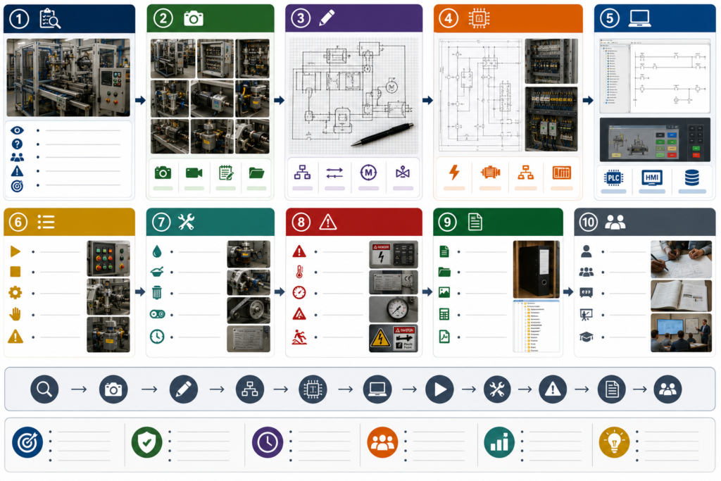
Some machines arrive with complete electrical drawings, software backups, manuals, spare-parts lists, and operating instructions.
Others arrive with a faded schematic from 2008, a PLC password nobody knows, and a cabinet full of wires that no longer match the labels.
Documenting an undocumented machine is not simply an administrative task. It is a controlled investigation. You are trying to understand what the machine actually does, how it fails, and how it can be restored without creating new risks.
The worst approach is waiting until the machine breaks down. Start while it still runs.
Begin With the Purpose of the Machine
Before tracing wires or opening PLC software, describe the machine in plain language.
Record:
- What the machine produces or processes
- Its main operating stages
- What enters and leaves the machine
- Which utilities it requires
- Who normally operates it
- Which machines connect to it
- What happens before and after it in production
Create a simple sequence description.
For example:
- Operator loads the product.
- Guard closes and is confirmed.
- Conveyor moves the product into position.
- Clamp extends.
- Process cycle begins.
- Clamp retracts.
- Product exits the machine.
This first version does not need to be perfect. Its purpose is to give structure to the investigation.
Photograph Everything Before Touching Anything
Take clear photographs of the complete machine, control cabinet, operator panel, sensors, motors, valves, junction boxes, cable routes, and nameplates.
Photograph components close enough that catalogue numbers can be read.
Also record:
- PLC model
- HMI model
- Power supplies
- Drives and servo controllers
- Safety relays or safety PLCs
- Network switches
- Remote I/O
- Pneumatic valve manifolds
- Motor and gearbox plates
Do not rely on memory. After several hours inside a crowded cabinet, similar cables and modules begin to look identical.
Photographs also provide evidence of the original condition before any changes are made.
Create a Machine Asset List
Build a spreadsheet listing every important component.
Useful columns include:
- Device name
- Manufacturer
- Part number
- Function
- Supply voltage
- Location
- Communication address
- Connected equipment
- Available spare
- Lifecycle status
- Notes
The naming does not need to match the existing machine perfectly at first. Use temporary identifiers such as M1 Conveyor Motor, B3 Entry Sensor, or Y2 Clamp Valve.
Apply temporary labels where permitted. Consistent names will make every later document easier to create.
Find and Verify the Software
Search company servers, maintenance laptops, USB drives, machine-builder folders, and old emails for PLC, HMI, robot, drive, and safety-controller projects.
Do not assume the newest file name is the correct version.
Record:
- Programming software
- Software version
- Controller type
- Firmware version
- Project password status
- Upload availability
- Online-to-offline comparison result
- Date the backup was verified
Where supported and authorised, upload the current controller program before making changes. Save an untouched backup with the date and machine state clearly recorded.
Remember that an uploaded PLC program may not contain all comments, symbols, hardware files, safety information, or HMI source files. A successful upload is valuable, but it may not recreate the original engineering project completely.
Store verified backups in approved company storage, not only on one technician’s laptop.
Build the I/O List
The I/O list connects the physical machine to the control program.
For each PLC point, document:
- PLC address or tag
- Signal description
- Device type
- Normally active state
- Terminal number
- Cable or wire number
- Physical location
- Relevant alarm or interlock
Walk through the machine while monitoring the PLC online.
Operate sensors individually where it is safe to do so. Confirm which input changes. Use manual controls to identify outputs, but never force outputs casually on a live machine.
An output may start a motor, move a cylinder, release a clamp, or energise equipment outside your field of view.
Use controlled testing with appropriate isolation, supervision, and communication.
Reconstruct the Electrical Drawings
Start with the control cabinet rather than trying to draw the entire machine at once.
Create drawings in manageable sections:
- Incoming power
- Control power supplies
- PLC and I/O
- Motor starters and drives
- Safety circuit
- Operator controls
- Field sensors
- Pneumatic valves
- Network connections
Trace one circuit at a time from the power source to the field device.
Mark uncertainty clearly. Use notes such as “unverified connection” rather than inventing an answer to make the drawing look complete.
Wire colours should not be treated as proof. Old machines may have been modified repeatedly, and a wire may no longer serve its original purpose.
Where isolation and company procedures permit, continuity testing can help confirm hidden or unlabelled connections.
Create a Network Map
Modern machines may contain several devices communicating over Ethernet or fieldbus networks.
Document:
- Device name
- IP address
- Subnet
- Protocol
- PLC connection
- Switch port
- Device firmware
- Configuration software
- Replacement procedure
Include remote I/O, HMIs, drives, robots, vision systems, barcode readers, gateways, printers, and links to plant systems.
Also note which devices use fixed addresses and what happens after replacement. Some equipment requires a device name, memory card, parameter download, or hardware configuration before it reconnects.
Record How the Machine Fails
Operators and experienced technicians often know more about the machine than the available files.
Ask:
- Which alarms are misleading?
- What usually fails first?
- Which sensors require frequent adjustment?
- What happens after a power cut?
- Which sequence commonly becomes stuck?
- Are there temporary bypasses?
- Which faults require a particular restart order?
- Which spare parts do not work without configuration?
Convert this knowledge into a troubleshooting guide.
A useful fault entry should include:
- Visible symptom
- HMI alarm
- Likely causes
- Checks to perform
- Relevant inputs and outputs
- Safe recovery procedure
- Parts commonly required
Avoid instructions such as “reset several times until it starts.” Document the actual conditions preventing the reset.
Document Safety Separately
Do not reverse-engineer safety functions casually.
Identify emergency stops, guard switches, light curtains, safety relays, safety PLCs, contactor feedback circuits, safe drive functions, and pneumatic isolation devices.
Record what you can verify, but involve appropriately qualified personnel when safety design, validation, or modification is required.
Never assume the PLC program represents the complete safety function. Some safety circuits may be hardwired, distributed across several devices, or modified outside the drawings.
Any discovered bypass or undocumented safety change should be escalated immediately.
Create a Practical Machine Folder
The final documentation should be easy to use during a breakdown.
A useful machine folder contains:
- Machine overview
- Sequence of operation
- Electrical drawings
- I/O list
- Component list
- Network map
- Verified software backups
- Drive and instrument parameters
- Alarm list
- Troubleshooting guide
- Spare-parts list
- Supplier contacts
- Revision history
Do not hide everything inside one 300-page PDF. Organise documents clearly and use searchable file names.
Treat Documentation as a Living System
The first version will contain mistakes and unanswered questions. That is normal.
Mark the document revision and include a section for outstanding verification. Update the files whenever wiring, software, components, or operating sequences change.
The objective is not to produce beautiful drawings that become outdated immediately. It is to create a reliable technical record that improves with every repair and modification.
An undocumented machine will not become fully understood in one day. Start with the systems that would cause the longest downtime, verify every important assumption, and document what the machine actually does—not what someone believes it was originally designed to do.