A motor is not usually connected directly to power by a simple switch; it is switched by a starter, whose heart is a contactor — an electrically operated switch that connects and disconnects the motor’s power. Understanding the starter and its power circuit is essential, because much motor troubleshooting involves the starter: the contactor that switches the power, the protection that guards the motor, and the path the power takes from supply to motor.
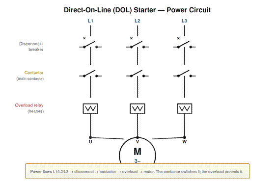
Figure 6.1 — A direct-on-line (DOL) starter power circuit. Power flows from L1/L2/L3 through the disconnect, the contactor’s main contacts, and the overload relay to the motor. The contactor switches the power; the overload protects the motor.
The contactor
The contactor is an electrically operated switch that connects the motor to power. It has main contacts — heavy contacts that carry the motor current — that are opened and closed by an electromagnet, the contactor’s coil. When the coil is energized, it pulls the contacts closed, connecting the motor to power; when the coil is de-energized, a spring opens the contacts, disconnecting the motor. This lets a small control signal (energizing the coil) switch the large motor current (through the main contacts), and it lets the motor be controlled remotely and automatically by controlling the coil. The contactor is thus the switching heart of the starter: its main contacts carry and switch the motor power, and its coil, controlled by the control circuit, determines whether those contacts are open or closed. Understanding the contactor — main contacts switched by a coil — is central to understanding the starter, because the contactor is what actually connects and disconnects the motor, and many motor faults involve the contactor: contacts that are worn, pitted, or not closing properly, or a coil that is not being energized when it should be.
The direct-on-line power circuit
The simplest and most common starter is the direct-on-line (DOL) starter, which connects the motor directly to the full supply voltage. Its power circuit is straightforward: the three supply lines pass through a disconnect or circuit breaker (for isolation and short-circuit protection), then through the contactor’s main contacts (which switch the motor on and off), then through the overload relay (which protects against sustained overcurrent), and finally to the motor terminals. Following this path — supply, disconnect, contactor, overload, motor — traces how power reaches the motor and where each protective and switching element sits. Understanding the DOL power circuit is fundamental because it is the basic motor power circuit, and more complex starters are variations on it. When troubleshooting, tracing this path — checking that power is present at the supply, passes through the disconnect, is switched by the contactor, passes through the overload, and reaches the motor — localizes where in the power circuit a problem lies. The DOL power circuit is the essential model of how a motor is powered, and knowing it — the sequence of disconnect, contactor, overload, motor — is the basis for understanding and troubleshooting the motor’s power path.
The control circuit: start, stop, and seal-in
The contactor’s coil is operated by a control circuit, and the most common arrangement — three-wire control with a seal-in — is worth understanding because so much motor operation and troubleshooting involves it. In three-wire control, a normally-closed stop button and a normally-open start button, together with the overload’s normally-closed contact, control the coil, and a seal-in contact (one of the contactor’s own auxiliary contacts) keeps the coil energized after the start button is released.
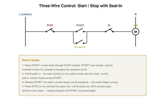
Figure 6.2 — Three-wire control with seal-in. Pressing START energizes the coil M through the closed STOP and OL contacts; M’s seal-in contact then holds the coil energized after START is released. Pressing STOP (or an overload trip) drops the coil and stops the motor until START is pressed again.
The sequence is the heart of it. Pressing START completes the circuit through the closed STOP contact, the now-closed START contact, and the closed overload contact, energizing the coil. The energized coil closes the contactor’s main contacts (starting the motor) and its seal-in contact (across the START button). Releasing START no longer matters, because the seal-in contact now keeps the coil energized — the motor keeps running. Pressing STOP, or an overload trip opening the overload contact, breaks the coil circuit, dropping the coil and stopping the motor, which stays stopped until START is pressed again. Understanding this three-wire control with seal-in — start energizes and seals in, seal-in holds, stop or overload drops out — is essential because it is the standard motor control arrangement, and many control-circuit faults involve it: a start button not making, a stop button stuck open, a failed seal-in contact (so the motor stops when start is released), or an overload contact not resetting. When a motor will not start or will not keep running, understanding the control circuit’s operation directs the diagnosis to the button, contact, or coil at fault.
Other starter types
Beyond DOL, several starter types address the large starting current of a directly connected motor. Star-delta starters, covered earlier, start the motor in star at reduced voltage before switching to delta. Soft starters use electronic control to ramp the voltage up smoothly, reducing the starting current and mechanical shock. Variable frequency drives, covered later, control the motor’s speed and also provide a gentle start. Each of these reduces the starting current or otherwise improves on the direct connection, at the cost of more complexity. Understanding that these starter types exist, and that they modify how the motor is connected during starting, helps in recognizing what kind of starter a motor has and how it operates. When troubleshooting, the starter type matters, because a star-delta or soft starter or drive has additional components and behaviors beyond the simple DOL starter, and knowing which type you have orients the diagnosis. But all of them ultimately connect the motor to three-phase power to run it, and the DOL power circuit — supply, switching, protection, motor — remains the underlying model, with the other types adding reduced-voltage or controlled starting to that basic arrangement.
Why a contactor, not a switch
It is worth understanding why motors are switched by contactors rather than simple manual switches, because the reasons explain much about motor control. A contactor, being coil-operated, can be controlled remotely and automatically — by a control circuit with start and stop buttons anywhere, by automatic controls, by protective devices — rather than requiring someone to physically operate a switch at the motor. This enables remote and automatic control, essential in industry. The contactor’s coil operation also enables the important safety feature that the motor drops out on loss of power or control voltage and does not restart by itself: because the coil must be energized to hold the contactor closed, a power loss de-energizes the coil and stops the motor, and it stays stopped (requiring a deliberate restart) rather than restarting unexpectedly when power returns. And the contactor lets protective devices stop the motor simply by interrupting the coil circuit. Understanding why a contactor is used — remote and automatic control, drop-out on power loss with no automatic restart, and easy protective interruption — explains its central role in motor control, and these features (especially the no-automatic-restart safety behavior) are important both to how motors are controlled and to troubleshooting the control circuit that operates the coil.
Scenario: the pitted contactor
A scenario shows a contactor fault. A motor ran intermittently and sometimes seemed weak, and the problem was traced to the contactor. Its main contacts, worn and pitted from long service and arcing, were making poor contact — sometimes one contact barely conducting, adding resistance or intermittently opening. This caused intermittent operation and, when one contact was making poor contact, effectively a partial single-phasing that weakened the motor. Understanding the contactor — that its main contacts carry the motor current and must make good contact — explains how worn contacts cause these problems: poor contact adds resistance or interrupts a phase, causing weak or intermittent operation. Inspecting the contactor revealed the pitted contacts, and replacing the contactor (or its contacts) restored reliable operation. This scenario shows a common starter fault — worn contactor contacts — causing intermittent and weak operation, diagnosed through understanding that the contactor’s main contacts must make good contact to carry the motor current properly. It reinforces that the contactor is a frequent troubleshooting target, its contacts subject to wear and pitting from switching the motor current, and that poor contacts cause recognizable problems — intermittent operation, weakness, effective single-phasing — that inspecting and servicing the contactor resolves. The contactor, as the switching heart of the starter, is a real and common source of motor circuit faults.
Tracing the power path in troubleshooting
When troubleshooting the power circuit, tracing the power path from supply to motor is the systematic approach, and understanding how to do it localizes power-circuit faults. The path runs from the three-phase supply, through the disconnect or breaker, through the contactor’s main contacts, through the overload, to the motor. Tracing it means checking, safely, that power is present and correct at each stage: present at the supply, passing through the disconnect (on and not tripped), switched through by the contactor (contacts closed when the coil is energized), passing through the overload (not tripped and its contacts good), and reaching the motor. At each stage, power present before but absent after localizes a fault to that stage. This tracing — following the power from supply to motor and finding where it stops or degrades — systematically localizes a power-circuit fault to the disconnect, contactor, overload, or wiring between them. Understanding how to trace the power path applies the split-half principle to the power circuit: measuring at stages to find where power is lost, narrowing to the faulty element. It reinforces the DOL power circuit as the map for this tracing — supply, disconnect, contactor, overload, motor — and the systematic checking of each stage as the method for localizing where in the power path a fault lies, which is the core of power-circuit troubleshooting.
The starter as the motor’s interface
The starter is the motor’s interface to power and control, and seeing it this way clarifies its central role in both operation and troubleshooting. Through the starter, the motor is connected to power (via the contactor), protected (via the overload and short-circuit protection), and controlled (via the control circuit operating the contactor). So the starter is where the motor meets its power supply and its control system — the interface through which the motor is energized, guarded, and commanded. This central role makes the starter a frequent focus of troubleshooting, because problems in connecting, protecting, or controlling the motor are problems in the starter: a contactor not switching, protection tripping, a control circuit not operating. Understanding the starter as the motor’s interface — the point where power, protection, and control meet the motor — clarifies why so much motor troubleshooting involves the starter and orients the diagnosis to it when the problem is in energizing, protecting, or controlling the motor. It reinforces that the starter is not a peripheral component but the central interface between the motor and its power and control, so that understanding the starter — its contactor, protection, and control — is essential to motor work, and the starter is a primary area to examine when a motor problem involves how it is connected to power, protected, or controlled, which is a large fraction of motor problems.
Inspecting contactors as routine
A practical maintenance habit: inspect contactors routinely, because their contacts wear and are a common source of motor problems. The contactor’s main contacts switch the motor current, arcing each time, and over many operations they wear and pit, eventually making poor contact that causes intermittent operation, weakness, or effective single-phasing. Routinely inspecting contactors — checking the contacts for wear and pitting, the coil and mechanism for proper operation — catches developing contactor problems before they cause motor faults. This is part of preventive maintenance for the motor circuit: the contactor, being a wearing switching component, benefits from periodic inspection. Understanding the contactor’s role and its wear-prone contacts motivates this routine inspection, catching the contact wear that would otherwise progress to motor problems. It reinforces the contactor as a maintenance item: its contacts wear from switching the motor current, and routine inspection catches the wear before it causes faults, so that inspecting contactors periodically — for contact condition and proper operation — is good preventive practice, preventing the intermittent operation, weakness, and single-phasing that worn contactor contacts cause. Given how central the contactor is and how its contacts wear, routine contactor inspection is a worthwhile part of motor circuit maintenance, catching a common developing problem before it stops or damages the motor.