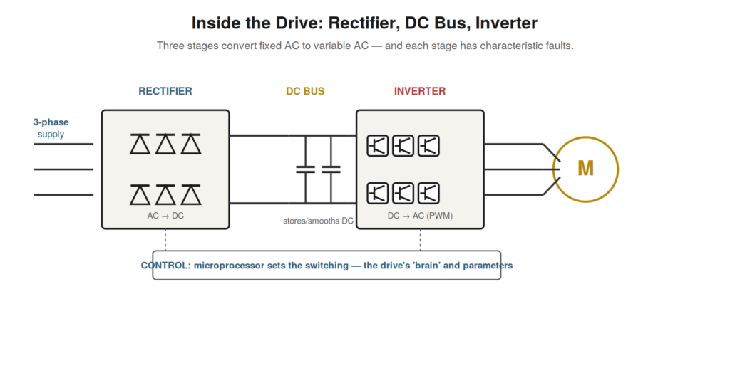
To troubleshoot a drive, you must understand its power structure —
the three stages through which it converts fixed AC to variable AC.
These stages, the rectifier, the DC bus, and the inverter, each have a
distinct function and characteristic faults, so understanding them is
the foundation for localizing where in the drive a problem lies. This
structure is common to the great majority of drives, and knowing it
turns the drive from a mysterious box into a comprehensible sequence of
stages.
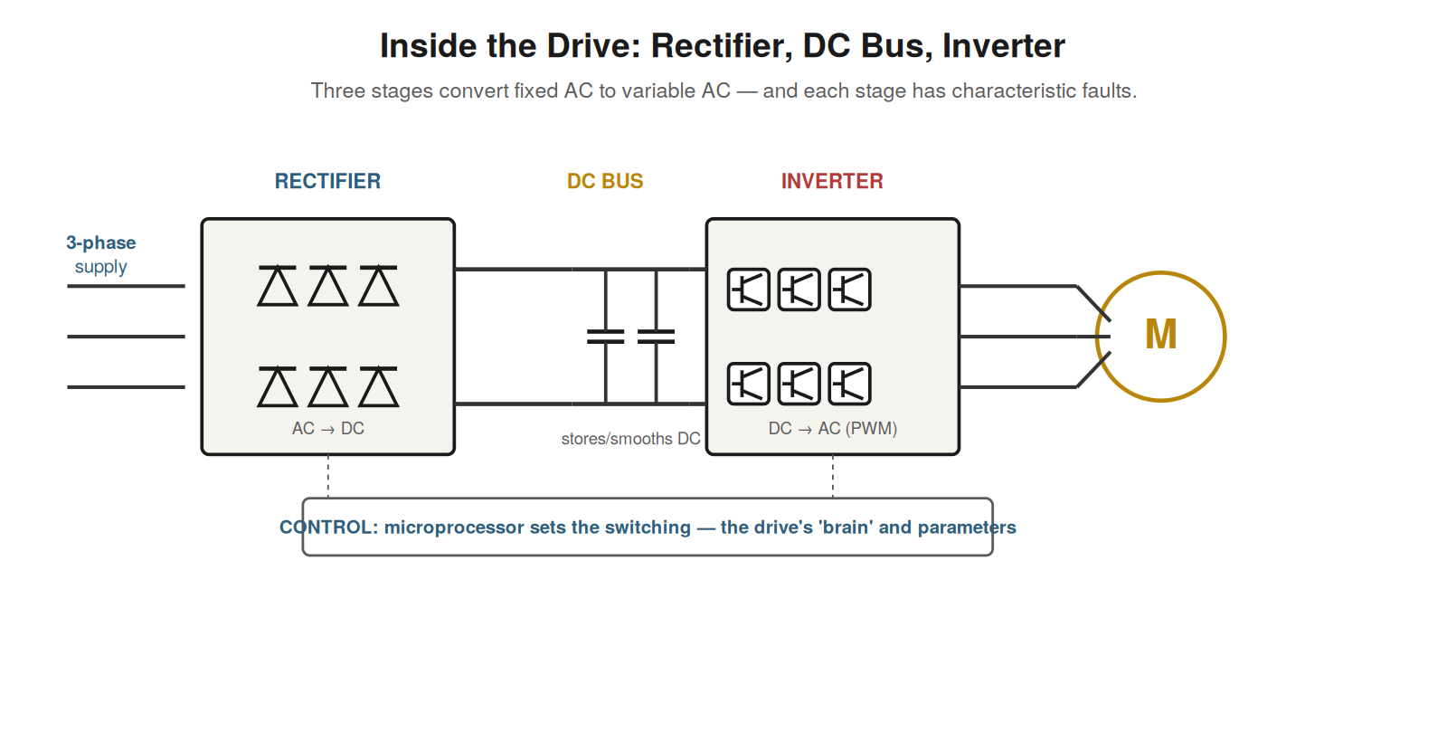
to DC, the DC bus stores and smooths it, and the inverter switches the
DC into a variable-frequency AC output. Each stage has characteristic
faults; the control system governs the switching.
The rectifier
The first stage, the rectifier, converts the incoming fixed-frequency
AC supply into DC. It typically uses diodes arranged to pass the
supply’s alternating voltage in one direction only, producing a DC
output from the three-phase AC input. This DC is the raw material the
rest of the drive works with: the drive cannot vary the supply’s
frequency directly, so it first converts the AC to DC, from which it
will later synthesize a new AC at whatever frequency it chooses. The
rectifier’s function is thus to provide DC from the AC supply, the first
step in the conversion. Understanding the rectifier — AC in, DC out, via
diodes — is the first part of understanding the drive’s power structure.
Faults associated with the rectifier and input include problems with the
incoming supply (missing phase, wrong voltage, imbalance), blown input
fuses, and failure of the rectifier components themselves. Because the
rectifier is the drive’s connection to the supply, input-side and supply
problems manifest here, and understanding the rectifier’s role —
converting the supply AC to the DC the drive uses — is the basis for
diagnosing problems at the drive’s input, where the drive draws its
power from the supply to begin the conversion process.
The DC bus
The second stage, the DC bus, stores and smooths the DC from the
rectifier, and it is in many ways the heart of the drive. The rectified
DC is not perfectly smooth, so the DC bus uses large capacitors to store
energy and smooth the voltage, providing a stable DC supply for the
inverter to work from. The DC bus voltage is a central quantity in the
drive: it reflects the state of the supply (a low bus voltage indicates
a supply problem) and the behavior of the motor (a motor regenerating
energy back into the drive raises the bus voltage). Because of this, the
DC bus voltage is one of the most important things to monitor in
troubleshooting, and two of the most common fault categories —
overvoltage and undervoltage — are defined by the DC bus voltage going
too high or too low. Understanding the DC bus — large capacitors storing
and smoothing the DC, its voltage a central indicator — is essential. It
is also the source of the drive’s characteristic safety hazard: the DC
bus capacitors store energy and remain charged after power is removed,
so the drive stays dangerous until the bus discharges. Understanding the
DC bus’s role — storing and smoothing the DC, its voltage central to the
drive’s operation and faults, and its stored energy a safety hazard — is
one of the most important parts of understanding the drive.
The inverter
The third stage, the inverter, is where the variable-frequency output
is created — it switches the DC bus voltage on and off rapidly to
synthesize AC at the desired frequency. Using fast electronic switches
(typically IGBTs), the inverter connects the motor terminals to the DC
bus in a rapidly switched pattern that, on average, produces an
alternating voltage at whatever frequency the drive chooses. This is the
stage that actually generates the variable-frequency output that
controls the motor’s speed, and it is the most electrically active and
stressed part of the drive. The inverter’s switching is controlled by
the drive’s control system, which determines the pattern and thus the
output frequency and voltage. Understanding the inverter — fast switches
synthesizing variable-frequency AC from the DC bus — completes the
picture of the drive’s power structure. The inverter is associated with
important faults: overcurrent (the inverter detects excessive output
current), output-stage failures, and the stresses its fast switching
places on the motor and cable. Because the inverter produces the output
to the motor, output-side faults and the inverter’s own faults manifest
here, and understanding the inverter’s role — switching the DC bus to
create the variable-frequency motor output — is the basis for diagnosing
output and inverter problems, completing the three-stage understanding
of how the drive converts fixed AC to variable AC.
Why convert to DC and back
A natural question about the drive’s power structure is why it
converts the AC supply to DC and then back to AC — why not modify the AC
directly? The answer lies in the difficulty of changing AC frequency
directly. The supply’s frequency is fixed, and there is no simple way to
change an AC waveform’s frequency directly. But it is straightforward to
convert AC to DC (rectification), and from DC, a new AC waveform of any
frequency can be synthesized by switching (inversion). So the drive
takes the indirect but practical route: convert the fixed-frequency AC
to DC, then synthesize new AC at the desired frequency from that DC. The
DC bus in between provides the stable DC that the inverter synthesizes
from. Understanding why the drive uses this AC-DC-AC structure — because
changing AC frequency directly is impractical, while converting to DC
and synthesizing new AC is practical — explains the drive’s fundamental
architecture. It clarifies that the three-stage structure is not
arbitrary but the practical means of achieving variable frequency: the
rectifier and DC bus provide DC as an intermediate, from which the
inverter synthesizes the variable-frequency output. This understanding
of why the structure exists — the AC-DC-AC path as the practical route
to variable frequency — illuminates the drive’s design and reinforces
the roles of the three stages in achieving the frequency conversion that
the drive’s purpose requires.
Scenario: localizing a fault by stage
A scenario shows the power structure guiding a diagnosis. A drive
faulted, and understanding its three-stage structure helped localize the
problem. The fault was an undervoltage on the DC bus, which —
understanding that the DC bus voltage derives from the supply through
the rectifier — pointed to the input side: the supply or rectifier
stage. Checking the input revealed a blown input fuse on one phase,
reducing the DC bus voltage and causing the undervoltage fault. The
structure understanding — DC bus voltage comes from the supply via the
rectifier, so a low bus points upstream — directed the diagnosis to the
input, where the blown fuse was found. Had the fault been overcurrent
(pointing to the inverter and output) or overtemperature (pointing to
the whole drive’s cooling), the structure would have directed the
diagnosis differently. This scenario shows the power structure —
rectifier, DC bus, inverter — serving as a map for localizing faults:
the fault type points to the relevant stage, directing the diagnosis.
Understanding the structure and each stage’s role lets you use the fault
to localize the domain, as the undervoltage pointed to the input side
and the blown fuse. It reinforces that understanding the drive’s power
structure is practically useful for troubleshooting, providing the map
that connects fault types to drive stages, so that a fault directs the
diagnosis to the relevant stage — here undervoltage to the input,
revealing the blown fuse — which is how the structural understanding
turns into efficient fault localization.
The pre-charge circuit
A detail of the drive’s power structure worth understanding is the
pre-charge circuit, which protects the drive when it powers up and can
be a source of faults. When a drive is first energized, its DC bus
capacitors are discharged, and connecting them directly to the rectified
supply would draw a huge inrush current to charge them suddenly — enough
to damage components. The pre-charge circuit prevents this by initially
charging the capacitors through a current-limiting element (a resistor),
gently bringing the DC bus up to voltage, then switching to the normal
full connection once charged. So the pre-charge circuit manages the
initial charging of the DC bus, protecting against inrush. A fault in
the pre-charge circuit — a failed resistor or the switching element —
can prevent the DC bus from charging properly, causing undervoltage or
power-up faults. Understanding the pre-charge circuit — gently charging
the DC bus at power-up to prevent inrush damage — explains a part of the
drive’s operation and a possible fault source. It reinforces that the DC
bus charging is managed by the pre-charge circuit, and that pre-charge
faults can cause DC bus charging problems (undervoltage, power-up
failures). Understanding the pre-charge circuit — its role in safely
charging the DC bus and its potential faults — adds to the understanding
of the drive’s power structure and provides another possible cause to
consider for DC bus and power-up problems, particularly undervoltage
faults where the bus fails to charge properly, which the pre-charge
circuit is responsible for.
The structure as a diagnostic map
The drive’s power structure serves as a diagnostic map, and
recognizing this consolidates its value for troubleshooting. The three
stages — rectifier, DC bus, inverter — each associated with
characteristic faults, provide a map that connects fault types to drive
locations: input and supply problems at the rectifier, over/undervoltage
at the DC bus, overcurrent and output problems at the inverter, with the
control system and cooling overlaying all. So when a fault occurs, the
structure maps it to a stage, directing the diagnosis. This mapping —
fault type to drive stage — is one of the most useful things the
structural understanding provides, turning the drive from an opaque box
into a mapped set of stages, each with its faults. Recognizing the power
structure as a diagnostic map consolidates its troubleshooting value:
understanding the stages and their faults lets you localize a fault to a
stage from its type, focusing the diagnosis. It reinforces that the
power structure is not just how the drive works but a map for diagnosing
it, connecting fault types to stages so the diagnosis is directed to the
relevant part of the drive. Understanding the power structure as a
diagnostic map — the stages and their characteristic faults guiding the
diagnosis — consolidates its practical value, making the structural
understanding a working tool that localizes faults to drive stages,
which is fundamental to efficient drive troubleshooting and a primary
reason the power structure is worth understanding thoroughly.