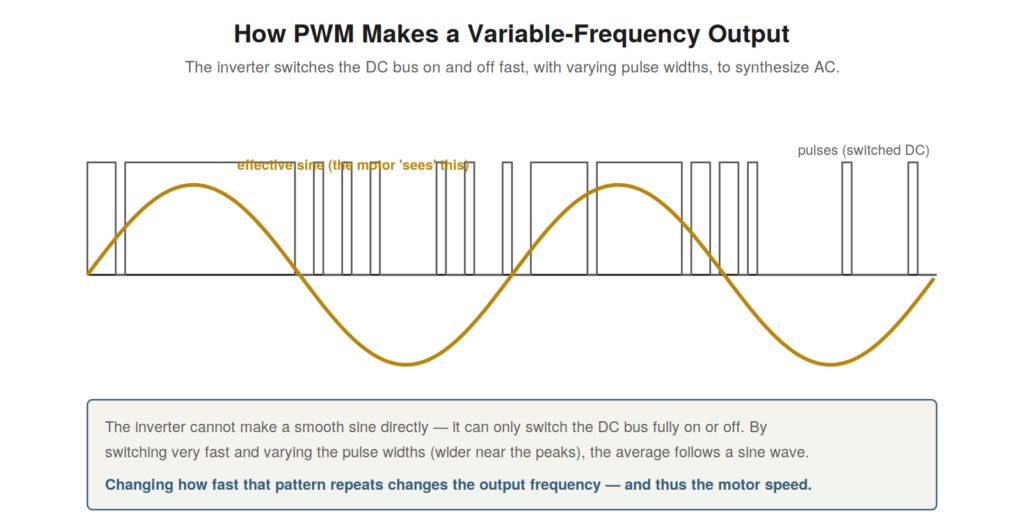
The inverter creates its variable-frequency output through
pulse-width modulation (PWM), and understanding PWM explains both how
the drive works and why it stresses the motor and generates electrical
noise. PWM is the technique by which the inverter, which can only switch
the DC bus fully on or off, synthesizes a smoothly varying AC output.
Understanding it demystifies the drive’s output and underlies several
important practical effects, so it is worth grasping clearly.
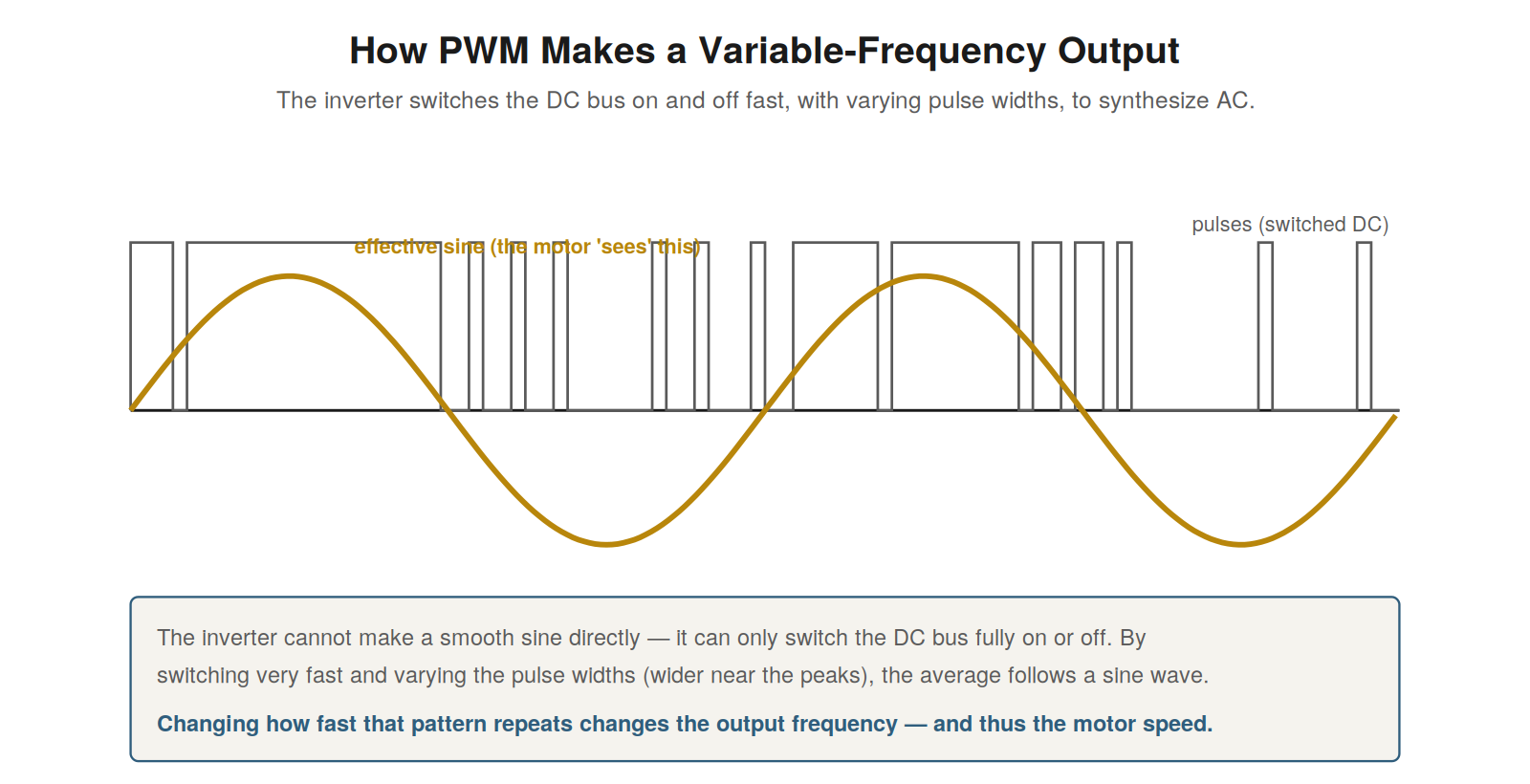
and off fast, varying the pulse widths, so the average follows a sine
wave. The motor, smoothing the pulses, effectively sees the sine.
Changing how fast the pattern repeats changes the output
frequency.
Switching to synthesize a sine
The inverter faces a basic constraint: its switches can only connect
the output fully to the DC bus or not — on or off — so it cannot produce
a smooth sine wave voltage directly. PWM solves this by switching very
rapidly and varying the width of the pulses: wider pulses (more on-time)
where the desired output is near its peak, narrower pulses where the
output should be small. The result is a train of pulses whose average,
over each short interval, follows the desired sine wave. The motor,
whose inductance smooths the rapid pulses, effectively responds to this
average — so it behaves as though supplied with a sine wave, even though
the actual voltage is a switched pulse train. Understanding this — the
inverter switches fast and varies pulse width so the average follows a
sine, and the motor smooths the pulses to see that average — explains
how the drive produces an effectively sinusoidal output from on-off
switching. It is the core technique of the modern drive, and
understanding it clarifies that the drive’s output is not a true sine
but a switched approximation, which the motor smooths, a fact that
underlies both how the drive works and the side effects (motor stress,
noise) of the fast switching that PWM requires.
Varying the frequency
PWM produces a variable-frequency output by varying how fast the
pulse pattern repeats, which is how the drive controls the motor’s
speed. The pulse pattern synthesizes one cycle of the output sine wave;
by repeating this pattern faster or slower, the drive produces a higher
or lower output frequency. To run the motor faster, the drive cycles the
pattern more quickly, producing a higher output frequency; to run it
slower, more slowly, producing a lower frequency. The drive also adjusts
the pulse widths to scale the output voltage with the frequency,
maintaining the volts-per-hertz relationship. So by controlling the
timing and widths of the PWM pulses, the drive controls both the
frequency and voltage of the output, and thus the motor’s speed and
torque. Understanding that the drive varies the output frequency by
varying the repetition rate of the PWM pattern — and the voltage by the
pulse widths — explains how PWM delivers the variable-frequency,
variable-voltage output that is the drive’s purpose. It connects the PWM
technique to the drive’s function: PWM is not just how the drive makes
AC, but how it makes variable AC, by controlling the pattern’s timing
and widths to set the frequency and voltage that determine the motor’s
speed and torque, which is the essence of what the drive does.
The side effects of fast switching
PWM’s fast switching, while enabling the drive’s operation, has side
effects that matter greatly in practice and troubleshooting — chiefly
stress on the motor and cable, and electrical noise. The switching is
very fast, producing voltage pulses with extremely rapid rise times, and
these fast-rising pulses stress the motor’s winding insulation
(especially with long cables, where reflections amplify the voltage) and
can cause currents through the motor’s bearings that damage them over
time. The fast switching also generates significant electrical noise —
electromagnetic interference — that can disturb the drive’s own control
signals, its communications, and nearby equipment. So the fast switching
that PWM requires, though essential to the drive’s function, brings
these side effects: insulation and bearing stress on the motor, and
electrical noise. Understanding these side effects of PWM’s fast
switching is important because they cause real problems that appear in
troubleshooting: motor insulation and bearing failures, and
noise-related faults that can be puzzling. These effects are addressed
by measures covered later (inverter-duty motors, output filters, good
grounding and shielding), but understanding that they stem from PWM’s
fast switching — an inherent aspect of how the drive works — explains
their origin and why drives require these mitigations that a simple
sine-wave supply would not, connecting the PWM technique to important
practical consequences for the motor, cable, and surrounding
equipment.
Switching frequency and its trade-offs
An important aspect of PWM is the switching frequency — how fast the
inverter switches — which involves trade-offs worth understanding. The
inverter switches many times per output cycle to synthesize the
waveform, and the rate of this switching (the switching or carrier
frequency) can often be set as a parameter. A higher switching frequency
gives a smoother output (the pulses approximate the sine more finely)
and quieter motor operation (less audible switching noise from the
motor), but it increases the inverter’s losses and heat (each switching
event dissipates some energy) and generates more electrical noise. A
lower switching frequency reduces the inverter’s losses and heat and the
electrical noise, but gives a coarser output and can make the motor
audibly noisier. So the switching frequency trades output smoothness and
motor quietness against inverter heat and electrical noise.
Understanding this trade-off is practically relevant: a high switching
frequency setting can contribute to drive overheating (more inverter
losses) and noise problems, while a low setting can cause motor audible
noise. In troubleshooting, the switching frequency parameter is thus
relevant to overheating and noise issues. Understanding the switching
frequency and its trade-offs — smoothness and quietness versus heat and
noise — explains this parameter’s effects and why it matters for drive
heat and noise, connecting the PWM technique to a practical parameter
that affects the drive’s thermal and noise behavior.
Scenario: the audible motor whine
A scenario connects PWM to an everyday observation. A drive-driven
motor emitted an audible whine that concerned the operators — was
something wrong? Understanding PWM explained it: the inverter’s
switching, at its switching frequency, causes the motor to emit sound at
that frequency, so a drive-driven motor often has an audible whine or
hum from the switching, which is normal, not a fault. The pitch
corresponds to the switching frequency. If the whine is objectionable,
raising the switching frequency (a parameter) moves the sound higher,
often to less audible or inaudible frequencies — at the cost of more
inverter heat and noise. So the motor whine was a normal consequence of
PWM switching, adjustable via the switching frequency. This scenario
shows PWM explaining the common observation of a drive-driven motor’s
audible whine: it comes from the switching, is normal, and can be
adjusted via the switching frequency parameter. Understanding PWM — the
switching that synthesizes the output — explains the whine and reassures
that it is normal, while pointing to the switching frequency as the
adjustment if it is objectionable. It reinforces that understanding PWM
demystifies drive behaviors like the motor whine, distinguishing normal
consequences of the switching (the whine) from actual faults, and
pointing to the relevant parameter (switching frequency) for adjustment,
so that a normal PWM-related observation is not mistaken for a problem,
and is adjusted appropriately if desired.
PWM and the motor’s smoothing
A key to understanding why PWM works is the motor’s own smoothing of
the pulses, and understanding this clarifies both the drive’s operation
and the imperfect nature of its output. The PWM output is a train of
voltage pulses, not a smooth sine, but the motor does not respond to the
individual pulses — its inductance smooths the current, so the motor
current is much smoother than the voltage pulses, following the average
(the intended sine) rather than the individual pulses. So the motor
effectively filters the PWM voltage into a smoother current, which is
why it runs on the PWM output much as it would on a sine wave. But the
smoothing is not perfect: some effect of the pulses remains, causing a
little extra heating and the harmonics associated with PWM.
Understanding the motor’s smoothing — its inductance filtering the
pulses into a smoother current following the average — explains why PWM
works despite the pulsed voltage, and why the output is close to but not
exactly a sine in effect. It reinforces that the motor’s inductance is
what makes PWM practical, smoothing the pulses so the motor runs on the
average, while the imperfect smoothing accounts for the extra heating
and harmonics of PWM operation. Understanding the motor’s role in
smoothing the PWM output — making the pulsed voltage into a smoother,
effectively-sinusoidal current — completes the understanding of how PWM
achieves near-sinusoidal motor operation from switched pulses, and why
the result, while close to sine-wave operation, carries the minor extra
heating and harmonic effects of the imperfectly-smoothed pulses.
PWM connects to the drive’s side effects
Understanding PWM connects to and explains the drive’s important side
effects, and recognizing this consolidates why PWM matters beyond being
the output method. PWM’s fast switching, essential to the drive’s
operation, is the root of several characteristic drive issues: the motor
insulation and bearing stress, the electrical noise, the extra motor
heating, and the switching-frequency trade-offs. All of these trace back
to the fast switching that PWM requires. So understanding PWM is
understanding the origin of these side effects, which are among the
drive’s most important practical concerns. Recognizing that PWM connects
to the drive’s side effects — the motor stress, the noise, the heating —
consolidates its importance: PWM is not just how the drive makes its
output but the source of the effects that cause many drive-related
problems. It reinforces that understanding PWM is practically valuable
because it explains these side effects, which appear throughout drive
troubleshooting (motor failures, noise problems, heating). Understanding
PWM — and recognizing that its fast switching is the root of the drive’s
characteristic side effects — consolidates its importance beyond the
output method: it is the origin of the motor stress, noise, and heating
that are central practical concerns in drive systems, so understanding
PWM illuminates not just how the drive works but why it causes the side
effects that much of drive troubleshooting and installation practice
must address, connecting the output technique to its wide-ranging
practical consequences.