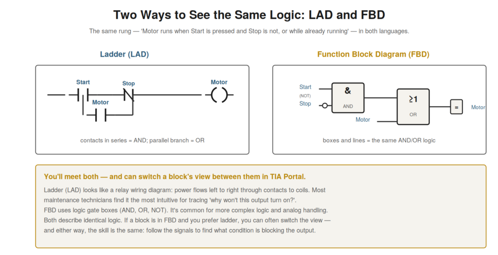
The logic in the program’s blocks is written in a programming
language, most commonly ladder logic (LAD) or function block diagram
(FBD), and being able to read these is the core skill of understanding a
program. Ladder resembles a relay wiring diagram and is intuitive for
many technicians; FBD uses logic gate boxes. Both express the same kind
of logic, and understanding how to read them lets you understand what
the program does, which is essential to diagnosis.
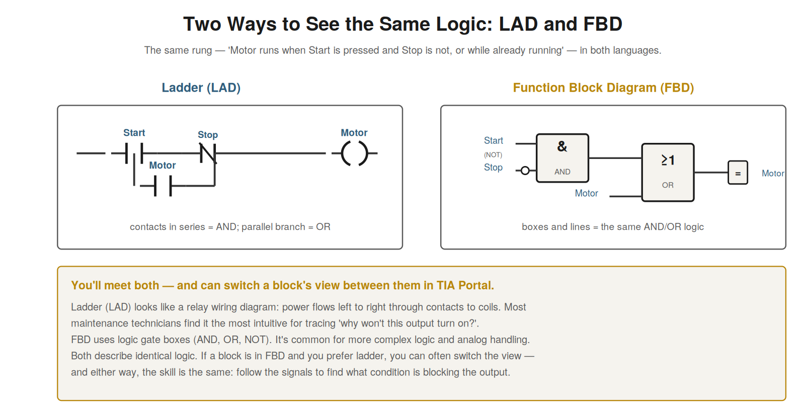
diagram (FBD). Ladder looks like a relay diagram — power flows left to
right through contacts to coils. FBD uses logic gate boxes (AND, OR,
NOT). Both describe identical logic; you can often switch a block’s view
between them.
Reading ladder logic
Ladder logic (LAD) is the most common and, for many technicians, the
most intuitive PLC language, because it resembles a relay wiring
diagram. A ladder program is a series of rungs, each like a circuit
running from a left power rail to the right: power flows through
contacts (conditions) to reach coils (outputs). A normally-open contact
passes power when its condition is true; a normally-closed contact
passes power when its condition is false; contacts in series form an AND
(all must pass); contacts in parallel form an OR (any path passes); and
the coil at the end is energized when power reaches it. So reading a
rung means following the power from left to right, seeing which
combination of contact conditions lets power reach the coil. This
resembles reading a relay circuit, which is why many technicians find it
intuitive. Understanding how to read ladder — power flowing through
contacts (conditions) to coils (outputs), with series as AND and
parallel as OR — is the core skill of understanding logic. It reinforces
that ladder is read like a relay circuit: power flows left to right
through contacts to coils, with the contact arrangement forming the
logic. Understanding how to read ladder logic — following power through
the contacts to the coil, interpreting series and parallel as AND and OR
— lets you understand what a rung does, which is the fundamental skill
of reading a program, especially valuable because ladder’s resemblance
to relay circuits makes it accessible to technicians and because tracing
power flow through a rung is exactly the technique used to diagnose why
an output is or is not energized.
Reading function block diagram
Function block diagram (FBD) expresses the same logic using logic
gate boxes rather than relay-style contacts, and understanding how to
read it lets you handle blocks written in this language. In FBD, logic
is built from boxes representing logic functions: an AND box outputs
true when all its inputs are true, an OR box when any input is true, a
NOT inverts a signal, and so on. Signals flow into and out of these
boxes along lines, and the arrangement of boxes forms the logic, ending
in an assignment to an output. So reading FBD means following the
signals through the logic boxes, understanding each box’s function (AND,
OR, NOT), to see how the output is determined. FBD is common for more
complex logic and for analog handling, and while it looks different from
ladder, it expresses the same kind of logic. Understanding how to read
FBD — signals flowing through logic gate boxes (AND, OR, NOT) to an
output — lets you read blocks in this language. It reinforces that FBD
uses logic boxes to express the logic, read by following signals through
the boxes, expressing the same logic as ladder in a different form.
Understanding how to read function block diagram — the logic gate boxes
and signal flow — complements reading ladder, so that you can understand
program logic whichever language it is written in, following the signals
through the FBD boxes just as you follow power through ladder contacts,
both leading to understanding how the output is determined, which is the
goal of reading the logic.
The same logic, different views
An important and reassuring point is that ladder and FBD express the
same logic in different forms, and you can often switch a block’s view
between them — understanding this reduces the intimidation of
encountering an unfamiliar language. The logic a program implements is
the same regardless of how it is displayed; ladder and FBD are just two
ways of showing it. A rung in ladder and the equivalent in FBD describe
identical behavior, in different visual styles. And in TIA Portal, you
can often switch a block’s display between ladder and FBD, so if a block
is in FBD and you find ladder more intuitive, you may be able to view it
as ladder. This means encountering FBD (or ladder) need not intimidate:
it is the same logic, and often viewable in your preferred form.
Understanding that ladder and FBD are interchangeable views of the same
logic — and often switchable — reduces the difficulty of reading
whichever you encounter. It reinforces that the two languages express
identical logic, and that you can often switch the view, so that the
choice of language need not be a barrier. Understanding that ladder and
FBD are the same logic in different views — often switchable in TIA
Portal — reassures that you can read a program’s logic regardless of its
display language, either by reading the language as presented (both
being learnable) or by switching to your preferred view, so that the
skill of reading logic — following the signals to understand the output
— applies to both languages, which are two representations of the same
underlying logic that determines what the program does.
Common instructions beyond contacts and coils
Real programs use more than simple contacts and coils, and
understanding a few common additional instructions helps you read actual
logic. Beyond the basic normally-open and normally-closed contacts and
output coils, common instructions include: set and reset coils (which
latch an output on or off until the other acts, rather than following
the rung continuously), timers (which produce an output after a time
delay, used everywhere for timing), counters (which count events),
comparison instructions (comparing values, like ‘is temperature greater
than a limit’), and math instructions (calculating values). These appear
as boxes or special symbols in the logic, and understanding their basic
function — what a timer, counter, or comparison does — lets you read
logic that uses them, which real programs invariably do. Understanding
these common instructions — set/reset, timers, counters, comparisons,
math — helps you read real logic beyond simple contacts and coils. It
reinforces that real programs use these common instructions, and that
understanding their basic function lets you read the logic that uses
them. Understanding common instructions beyond contacts and coils — the
timers, counters, comparisons, and set/reset that real logic uses —
equips you to read actual programs, which go beyond simple contact-coil
logic to use these instructions for timing, counting, comparing, and
latching, so that recognizing and understanding these common
instructions lets you follow the real logic of actual machines, which
invariably use timers, comparisons, and the other common instructions
alongside the basic contacts and coils.
Scenario: the interlock hidden in the logic
A scenario shows reading logic to find a hidden interlock. A machine
would not start, and monitoring showed the start rung false, with the
breaking condition being a memory bit — not an obvious physical input,
but an internal bit. To understand what set this bit, the technician
read the logic where it was controlled (found via cross-references), and
discovered it represented a complex interlock: the bit was true only
when several conditions across the machine were met (all guards closed,
no active faults, a reset performed). One of these — a required reset
after a previous fault — had not been done, so the interlock bit was
false, blocking the start. Reading the logic had revealed the interlock
and its unmet condition. Performing the reset satisfied the interlock,
and the machine started. This scenario shows reading logic to understand
an interlock bit and find its unmet condition. Understanding how to read
the logic let the technician trace an internal interlock bit to its
conditions and find the unmet one (a needed reset), which reading the
logic revealed. It reinforces that reading the logic — not just physical
inputs but internal bits and their controlling logic — reveals
interlocks and conditions that block operation. The scenario reinforces
the value of reading logic: the technician found a hidden interlock (an
internal bit set by several conditions) and its unmet requirement (a
reset) by reading the logic that controlled the bit, illustrating how
reading the logic, including internal bits and their conditions, reveals
the interlocks and requirements that a simple look at physical inputs
would miss.
Following logic across networks and blocks
A technique for reading real programs is following logic across
multiple networks and blocks, because the logic determining an output
often spans more than one rung, and understanding how to follow it is
essential. A single output’s behavior may depend on logic spread across
several networks (rungs) or even several blocks: one network might set
an intermediate bit, another use it, and the final output depend on the
combination. So to fully understand an output, you may need to follow
the logic across these — tracing an intermediate bit from where it is
set to where it is used, possibly across blocks. Cross-references are
the key tool here, letting you jump from a bit’s use to where it is set,
following the logic wherever it leads. So reading real logic often means
following it across networks and blocks, using cross-references to trace
the connections. Understanding how to follow logic across networks and
blocks — tracing intermediate signals with cross-references — is
essential to reading real, distributed logic. Understanding how to
follow logic across networks and blocks — using cross-references to
trace intermediate signals from where they are set to where they are
used — is essential for reading real programs, where an output’s logic
often spans multiple rungs and blocks rather than sitting in one place,
so that you can follow the full logic determining an output by tracing
its intermediate signals across the program with cross-references, which
is how you understand outputs whose controlling logic is distributed
across the program rather than contained in a single rung.
Reading logic as the central skill
Consolidating the logic-reading material, reading logic is the
central skill of understanding a program — the ability on which
diagnosis most depends — and appreciating this emphasizes developing it.
Everything about understanding what a program does comes down to reading
its logic: following the ladder or FBD to see how outputs are determined
by inputs and conditions. This is what lets you understand a machine’s
behavior, diagnose why an output is or is not on, and trace faults
through the logic. So reading logic is central: the more fluently you
read it, the better you understand programs and diagnose faults.
Developing this skill — reading ladder and FBD fluently, following the
logic to understand the outputs — is thus central to becoming an
effective maintenance technician. It is a skill that improves with
practice, reading real logic until it becomes natural. Understanding
reading logic as the central skill — on which understanding and
diagnosis most depend — emphasizes developing it through practice.
Understanding that reading logic is the central skill of understanding a
program — the ability on which diagnosis most depends — emphasizes
developing it through practice, so that you recognize fluent reading of
ladder and FBD as the core competence for understanding machine behavior
and diagnosing faults, and invest in developing it by reading real logic
until following the signals to understand the outputs becomes natural,
which is central to becoming an effective maintenance technician because
so much of diagnosis comes down to understanding what the program’s
logic does and why an output is in the state it is.