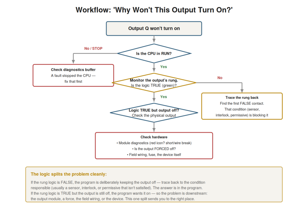
The most common diagnostic question a maintenance technician faces is
‘why won’t this output turn on?’ — a motor that will not start, a valve
that will not open, a lamp that will not light. TIA Portal, with live
monitoring, provides a systematic workflow to answer it, and this
workflow — which cleanly splits the problem into program and hardware —
resolves a large share of practical faults. Understanding it gives you a
reliable method for this most common of situations.
check the CPU is in RUN, then monitor the output’s rung. If the logic is
FALSE, trace back to the first false condition (the answer is in the
program). If the logic is TRUE but the output is off, the problem is
downstream (hardware, force, wiring).
First, is the CPU running?
The first check when an output will not turn on is whether the CPU is
even running, because if the CPU is stopped, nothing will work, and the
diagnosis goes straight to why it stopped. If the CPU is in STOP —
whether from a fault or deliberately — the program is not executing, so
no output driven by the program will turn on. So before investigating
the specific output, confirm the CPU is in RUN. If it is in STOP, the
problem is not the specific output but the stopped CPU, and the
diagnosis goes to the diagnostics buffer to find why the CPU stopped (as
covered earlier). Only if the CPU is running does it make sense to
investigate the specific output’s logic. Understanding this first check
— is the CPU in RUN? — ensures you do not chase a specific output when
the whole CPU is stopped. It reinforces checking that the CPU is running
before investigating a specific output, because a stopped CPU explains
any output being off, redirecting the diagnosis to the diagnostics
buffer. Understanding to first check whether the CPU is running — and to
go to the diagnostics buffer if it is stopped — is the correct starting
point for the output-won’t-turn-on diagnosis, ensuring you address a
stopped CPU (a whole-machine problem) before investigating a specific
output, so that the diagnosis starts by confirming the CPU is actually
running the program, without which no output-specific investigation
would make sense.
Is the logic true or false?
With the CPU running, the key diagnostic step is to monitor the
output’s rung and determine whether its logic is true or false, because
this cleanly splits the problem into two very different situations.
Monitoring the output’s rung shows whether the logic is satisfied —
whether the path to the output is energized (true) or broken (false).
This single observation splits the problem: if the logic is false, the
program is deliberately keeping the output off (some condition is not
met), and the answer lies in the program — trace back to the unmet
condition. If the logic is true, the program wants the output on, so the
problem is not the program but downstream — in the output hardware, a
force, or the wiring. So monitoring the rung’s logic state divides the
diagnosis into a program problem (logic false) or a hardware problem
(logic true), directing you to the right place. Understanding this key
split — is the rung’s logic true or false? — is the heart of the output
diagnosis. It reinforces that monitoring the output’s rung to see
whether its logic is true or false splits the problem into a program
issue (false — trace the logic) or a hardware issue (true — check
downstream). Understanding this true-or-false split — the key diagnostic
step that divides the problem into program or hardware — is the heart of
the output-won’t-turn-on workflow, because it sends you decisively to
the right domain: if the logic is false, into the program to find the
blocking condition; if true, downstream to the hardware, which cleanly
separates the two very different situations and focuses the diagnosis
correctly.
Following each branch
Each branch of the split — logic false or logic true — leads to a
clear next step, and understanding both completes the output diagnosis
workflow. If the logic is false, you trace the rung back to find the
first false condition — the contact that is breaking the path — and that
condition (a sensor not made, a permissive not satisfied, an interlock
not met, a fault bit set) is what is preventing the output. You then
investigate why that condition is not satisfied, which is the real
cause. If the logic is true but the output is still off, you check
downstream: the output module’s diagnostics (is there a red icon, a
short, a wire break?), whether the output is forced off (an override),
and the field wiring and the device itself. So the false branch leads
into the program (trace to the blocking condition), and the true branch
leads to the hardware (module, force, wiring, device). Understanding
both branches — trace the logic for false, check the hardware for true —
completes the workflow. It reinforces that a false rung is diagnosed by
tracing back to the blocking condition in the program, while a true rung
with an off output is diagnosed by checking the downstream hardware,
force, and wiring. Understanding how to follow each branch — into the
program for false logic, to the hardware for true logic — completes the
output-won’t-turn-on workflow, giving you a reliable method for this
most common diagnostic question: check the CPU, monitor the rung, and
follow the true-or-false split to either the blocking condition in the
program or the hardware problem downstream, which resolves a large share
of the practical faults a maintenance technician encounters.
Set/reset and the output being held
A subtlety in diagnosing why an output will not turn on involves
set/reset instructions, and understanding it prevents confusion when the
simple rung-tracing does not fit. Most outputs follow their rung
continuously (on when the rung is true, off when false), and the
standard trace-the-rung technique applies. But some outputs are
controlled by set and reset instructions: a set instruction latches the
output on (and it stays on even if the setting condition goes away), and
a reset instruction latches it off. For such an output, it is not enough
to look at one rung; you must find both where it is set and where it is
reset, because a reset elsewhere may be holding it off despite a set
condition, or vice versa. So for a set/reset-controlled output, the
diagnosis involves finding both the set and reset logic
(cross-references help), not just one rung. Understanding this subtlety
— that set/reset outputs need both the set and reset logic examined —
prevents confusion when a simple rung trace does not explain the output.
It reinforces that set/reset-controlled outputs are diagnosed by finding
both the set and reset conditions (via cross-references), because either
can hold the output, unlike a simple rung-following output.
Understanding set/reset and the output being held — that latched outputs
need both set and reset logic examined — handles a case where the simple
rung-tracing technique needs extension, so that when an output is
controlled by set/reset rather than a simple coil, you know to find both
the set and reset logic (using cross-references) to understand what is
holding the output in its state, which prevents the confusion of tracing
one rung when the output is actually latched by set/reset logic
elsewhere.
Scenario: true logic, dead output
A scenario shows the workflow’s hardware branch. An output — a
solenoid valve — would not energize, and the technician applied the
workflow. The CPU was in RUN. Monitoring the valve’s rung, they found
the logic true — the program wanted the valve on, all conditions met,
the coil shown energized in the logic. Yet the valve was not operating.
This true-logic-but-off situation directed them downstream, past the
program, to the hardware. Checking the output module’s diagnostics, they
found a fault on that channel: a wire break. The field wiring to the
valve had an open circuit, so although the program energized the output,
no signal reached the valve. Repairing the broken wire restored
operation. The workflow’s true-logic branch had correctly sent them to
the hardware, where the wire break was. This scenario shows the
workflow’s hardware branch: true logic with a dead output pointing
downstream to a wiring fault. Understanding that true logic with an off
output means a hardware problem directed the technician past the program
to the wire break. It reinforces that the true-logic branch of the
output workflow points to hardware — the module, force, or wiring —
where the problem lies when the program wants the output on. The
scenario reinforces the output workflow’s clean split: true logic but a
dead output sent the technician to the hardware, where a wire break was
found, illustrating how the workflow correctly directs you downstream to
the hardware when the logic is true, just as it directs you into the
program when the logic is false, sending you to the right place either
way.
The output that turns on then off
A variation of the output problem is an output that turns on then
immediately off (or flickers), and understanding how to diagnose this
handles the case where the output is not simply stuck off. Sometimes an
output does energize but then drops out immediately, or cycles on and
off — not simply failing to turn on, but failing to stay on. This points
to a condition that becomes false right after the output acts: perhaps a
fault that trips as soon as the output starts (an overload, a feedback
that is not received), or an interlock that opens in response. To
diagnose, you monitor the rung and watch what happens when it turns on:
which condition goes false to drop it out? A watch table capturing the
relevant signals helps catch the fast sequence. So the flickering or
dropping output is diagnosed by watching what condition changes to drop
it, often a protective response to the output acting. Understanding how
to diagnose the output that turns on then off — watching what condition
drops it out — handles this variation. Understanding how to diagnose the
output that turns on then off — by watching what condition becomes false
to drop it out, often a protective trip or a missing feedback triggered
by the output acting — handles the variation where the output fails to
stay on rather than failing to turn on, so that you catch the condition
that drops the output (using monitoring and a watch table to see the
fast sequence), which diagnoses the flickering or dropping-out output by
identifying what turns it off right after it turns on, a different
situation from the simply-stuck-off output but diagnosable with the same
monitoring tools applied to the dynamic behavior.
A workflow you’ll use constantly
Consolidating the output-workflow material, this is a workflow you
will use constantly — the output-won’t-turn-on question arises in
countless forms — and appreciating its broad applicability emphasizes
mastering it. The specific question ‘why won’t this output turn on?’
underlies a huge range of practical faults: a motor that will not start,
a valve that will not open, a lamp that will not light, an actuator that
will not move — all are outputs not turning on. So the workflow — check
the CPU, monitor the rung, split on true/false logic, follow to the
program or the hardware — applies to all of them, a constantly useful
method. Mastering it means having a reliable approach to a large
fraction of the faults you will encounter. So this workflow, more than
most, repays mastery through constant application. Understanding it as a
workflow you will use constantly — applicable to countless output faults
— emphasizes mastering it thoroughly. Understanding the
output-won’t-turn-on workflow as one you will use constantly — because
the question underlies a huge range of practical faults, from motors to
valves to lamps to actuators — emphasizes mastering it thoroughly, so
that you develop this reliable method (check the CPU, monitor the rung,
split on the logic’s truth, follow to the program or the hardware) into
a well-practiced approach, because it applies to such a large fraction
of the faults you will encounter that mastering it repays the effort
many times over through its constant application to the countless forms
of the output-not-turning-on problem.