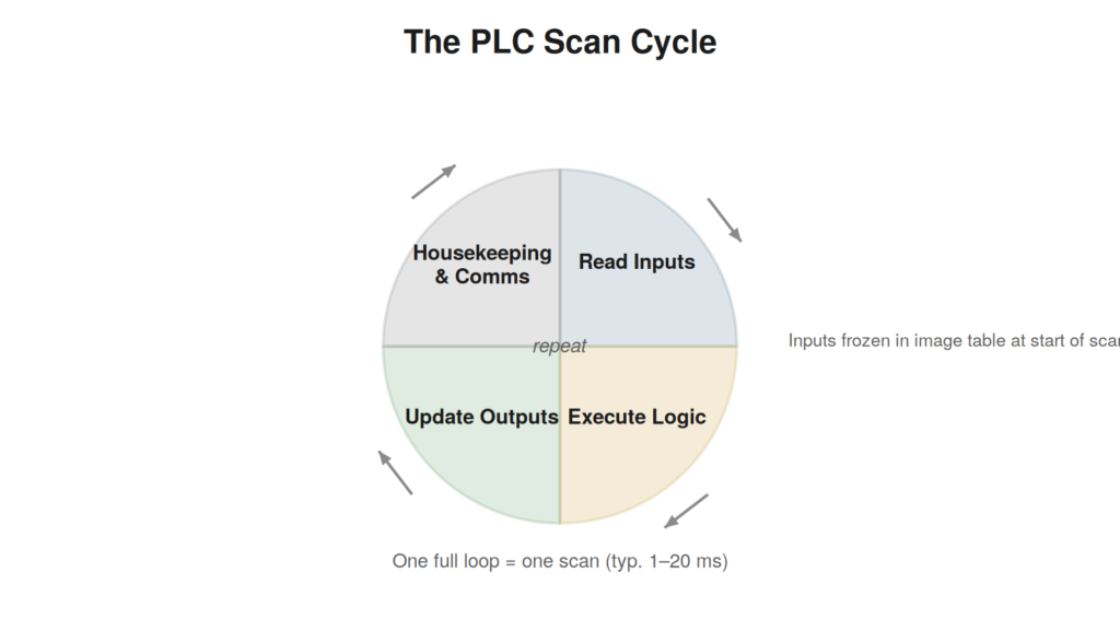
You do not need to be a controls engineer to troubleshoot a PLC, but
you do need an accurate mental model of what the controller is doing. A
programmable logic controller is, at heart, a ruggedized computer that
repeats one loop forever: it reads the state of its inputs, runs a
program that decides what the outputs should be, and writes those
decisions to its outputs. Then it does it again, typically hundreds of
times per second.
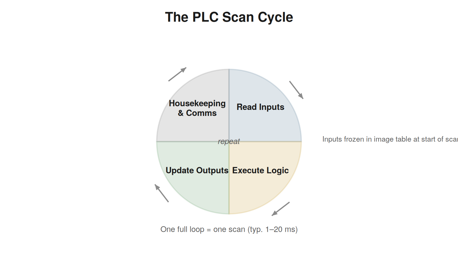
table at the start of each scan; logic runs against that frozen
snapshot; outputs are updated at the end.
The scan cycle and why it matters for you
Understanding the scan explains behavior that otherwise looks like
magic. At the start of each scan the CPU copies the physical input
states into an internal input image table. Your logic runs against that
snapshot, not against the live terminals. At the end of the scan it
copies the results to the output image table and on to the physical
outputs. A fast input pulse shorter than one scan can be missed
entirely. A forced value stays forced regardless of the field. And when
you go online to watch a tag, you are watching the image table — which
is exactly why comparing the image value against the physical terminal
is such a powerful diagnostic split.
The building blocks
| Block | What it does | What fails / what to check |
|---|---|---|
| CPU / processor | Runs the program, handles the scan, stores faults | Major faults halt the scan; check the fault indicator and diagnostic log |
| Power supply | Feeds the backplane and often field 24 V DC | Sagging or dead PSU causes random dropouts; measure under load |
| Input modules | Convert field signals to logic states | Blown channel, wrong sink/source, loose terminal |
| Output modules | Drive field loads from logic states | Failed channel, blown fuse, welded relay, wrong voltage type |
| Communication ports | Link to I/O, drives, HMI, networks | Bad cable, IP conflict, duplicate address, switch fault |
| Memory / program | Holds logic and retained data | Corruption is rare; mismatched program version is common |
Two families you will meet most
This book focuses on the two platforms a maintenance technician in
most industries encounters constantly. On the Allen-Bradley (Rockwell
Automation) side that means the Logix family — ControlLogix and
CompactLogix programmed in Studio 5000 Logix Designer — and the smaller
Micro800 series in Connected Components Workbench. On the Siemens side
it means the SIMATIC S7-1200 and S7-1500 controllers programmed in the
TIA Portal, and the older but still widespread S7-300/400 in STEP 7. The
vocabulary differs — Rockwell calls a program download a ‘download’,
Siemens speaks of the ‘diagnostic buffer’ — but the physics underneath
is identical. Where a procedure differs between the two, this book calls
it out explicitly.
VENDOR NOTEThroughout this book, ‘AB’ refers to Allen-Bradley / Rockwell and |
What actually happens in one scan
It is worth slowing down and walking through a single scan in detail,
because almost every subtle PLC behavior falls out of this sequence.
When the scan begins, the processor reads every physical input and
stores those states in a dedicated area of memory — the input image
table. Crucially, it takes this snapshot all at once and then works only
from the snapshot. If an input changes halfway through the scan, the
logic will not see that change until the next scan begins. This is not a
flaw; it makes the logic deterministic. Every rung in a given scan sees
exactly the same input picture, so the outcome does not depend on when
in the scan a particular rung happens to run.
Next, the processor executes the program from top to bottom, rung by
rung. Each rung reads from the image tables and internal memory, and
writes its results back to memory — including the output image table.
Because execution is top to bottom, order matters: a value written by an
early rung is available to a later rung in the same scan, but a value
written by a later rung will not be seen by an earlier rung until the
next scan. This ordering is behind a class of subtle logic behaviors,
and it is why ‘one scan of delay’ is a phrase you will hear controls
engineers use.
Finally, the processor copies the output image table to the physical
output terminals, then handles housekeeping — communications,
diagnostics, internal checks — before starting the loop again. The whole
cycle typically takes a few milliseconds. For a maintenance technician,
three consequences matter most: the controller acts on a snapshot, not
on the live field; a signal shorter than one scan can be missed; and the
tag you watch online is the image, which you can compare against the
physical terminal to localize a fault.
Scan time and why it sometimes matters
Most of the time you will not think about scan time, but occasionally
it explains a fault. If a program grows very large or contains
inefficient logic, the scan can lengthen to the point where fast events
are missed or where a watchdog timer — a safety mechanism that faults
the processor if a scan takes too long — trips. A watchdog fault on an
Allen-Bradley controller or a cycle-time fault on a Siemens CPU points
you at scan time. More commonly, scan time matters for high-speed
counting: an ordinary digital input cannot reliably catch pulses faster
than the scan, which is why encoders and fast sensors use dedicated
high-speed inputs that bypass the normal scan sampling.
Memory, tags, and addresses
Older and smaller controllers use numbered addresses — an input might
be I:1/0, an internal bit B3:0/2. Modern Logix and Siemens controllers
use named tags — Conveyor_Run, Infeed_Prox — which are far easier to
read but mean you must know the tag name to find a signal. When
troubleshooting, the practical skill is moving between the physical
world and the tag: this terminal on this module corresponds to this tag
in the program. The module’s position in the rack or network and the
channel number give you the physical address; the program’s I/O
configuration ties that to the tag name. Keeping that mapping straight
is half the battle when a fault spans the boundary between field and
logic.
RETAINED VERSUS NON-RETAINEDSome data survives a power cycle (retained) and some does not. After |
Racks, remote I/O, and the physical layout
Knowing how the hardware is physically arranged saves real time when
a fault spans modules. A traditional system places the processor and I/O
modules together in a rack or chassis connected by a backplane, with
field wiring landing on terminals at each module. Modern systems often
distribute I/O: the processor sits in one location and additional I/O
lives in remote racks or compact blocks out near the machine, linked by
a network. This layout matters because a fault can be local to a module,
or it can be in the network path to a remote rack, and the two look
different in the diagnostics. When several I/O points fail together, ask
whether they share a module, a rack, or a network segment — the shared
element is usually the fault, and knowing the physical layout tells you
what they share.
How I/O maps to the program
The bridge between a physical terminal and a program tag is the I/O
configuration, and understanding it lets you cross the field-logic
boundary confidently. Each module occupies a known position — a slot in
a rack, a node on a network — and each channel on that module has a
number. The controller’s I/O configuration ties that physical position
and channel to an address or tag that the program uses. So a signal has
two identities: a physical one (this terminal, on this module, in this
position) and a logical one (this tag in the program). Troubleshooting a
fault that crosses the boundary means translating between them: the
program says tag Infeed_Prox is off; the I/O configuration says that tag
is channel 3 on the module in slot 4; so you go to slot 4, channel 3,
and meter that terminal. Fluency in this translation is what lets you
follow a fault from a screen to a screwdriver.
Power and grounding: the foundation everything sits
on
Beneath all the logic and I/O sits the power and grounding system,
and problems here masquerade as almost anything, which makes
understanding them valuable out of proportion to how often they are
discussed. The controller and its I/O depend on stable, adequate power —
typically a 24 V DC supply for the control system and field devices, fed
from the plant supply through a power supply unit. When that power sags,
becomes noisy, or is marginally sized for its load, the symptoms are
maddeningly varied: random dropouts, intermittent faults, devices that
work alone but fail together, resets with no logged cause. Because these
symptoms point everywhere, the power supply is often the last thing
checked when it should be among the first for any diffuse, hard-to-pin
fault. Measuring the supply voltage under real load — not unloaded —
reveals a supply that reads fine at rest but collapses when the system
draws current.
Grounding is the quieter half of the foundation. A proper ground
gives noise a path away from signals and gives fault current a safe
route, and a compromised ground — a loose grounding connection, a
missing bond, a ground shared badly between noisy and sensitive
equipment — admits the electrical noise that corrupts analog readings
and communications. Many intermittent analog and network faults that
resist every other explanation trace ultimately to grounding, because a
poor ground lets interference in that a good ground would have shunted
away. Grounding faults are hard to see because nothing is obviously
broken; the system works until noise arrives, then misbehaves in ways
that seem to have nothing to do with the ground. When diffuse
noise-related faults resist localization, the grounding system deserves
scrutiny even though it is invisible in the logic and the
diagnostics.
MEASURE UNDER LOADThe single most useful habit for power faults is to measure the |
A case file: the fault that only appeared after a power
cycle
A machine runs correctly for weeks, but after any power interruption
it comes back in a wrong state and must be manually corrected before it
will cycle. The specific trigger — a power cycle — is the clue that
points at the distinction between retained and non-retained data. Some
values in a controller survive a power loss while others reset, and a
machine that misbehaves only after power is restored is often relying on
a value that should have persisted but did not, or that reset when the
logic expected it to hold. Investigating, the technician finds a
position or state value that the logic assumed would be retained across
power loss but which was configured as non-retentive, so on every
power-up it returned to zero and left the machine in an inconsistent
state. Correcting the retention configuration so the value persists
across power loss resolves the wrong-state-on-restart behavior. The case
illustrates why the retained-versus-non-retained distinction matters in
practice: a fault that appears only after a power cycle, and
specifically a machine returning in a wrong or inconsistent state,
points at data retention rather than at any hardware fault, and the fix
lies in how the relevant values are configured to survive power loss
rather than in any physical component.
The controller mode and why it stops a machine
cold
A controller can be running its program, or it can be stopped, and a
stopped controller will not operate the machine no matter how healthy
every other part of the system is — a fact worth internalizing because
it explains a class of otherwise baffling situations. If a controller is
in a program or stop mode rather than run, whether because a key-switch
was left in the wrong position, a fault put it there, or someone stopped
it and forgot, the machine simply will not go, and every input, output,
and network can be perfect while nothing happens. Reading the
controller’s mode is therefore an early check: a controller not in run
mode is the reason the machine is down, and the question becomes why it
is not running — a fault that stopped it, a mode selection left wrong,
or a deliberate stop. This is why the LED sweep includes the processor
mode near the start, because a stopped controller presents as a
completely dead machine that no amount of I/O or network troubleshooting
will revive, and recognizing ‘the controller is not in run’ immediately
as the cause redirects the whole investigation to why it is stopped
rather than to the field, saving a fruitless search through healthy
hardware for a fault that lives in the controller’s mode.