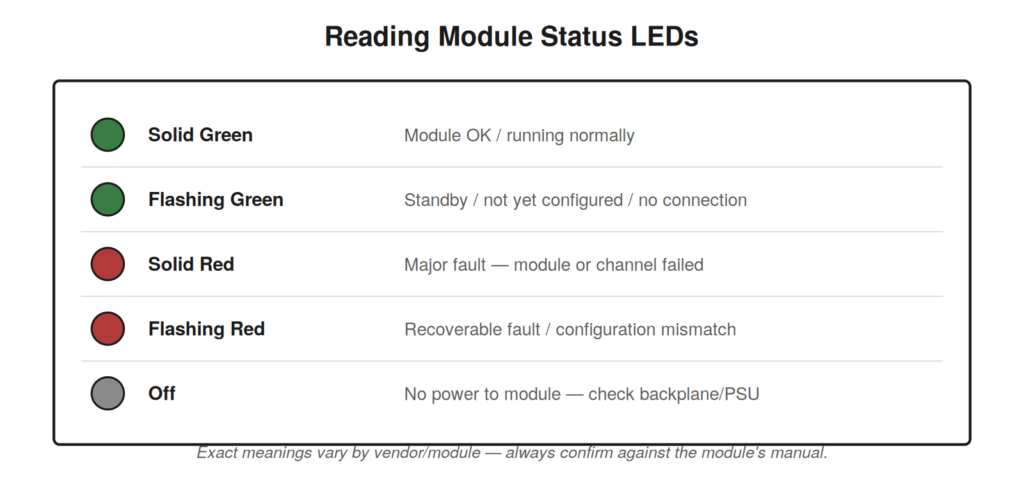
Long before you open the programming software, the controller is
already telling you a great deal through its indicator lights. Learning
to read them turns a blank stare at a rack into a quick triage. Every
module has status LEDs, and while exact meanings vary by product, the
pattern language is remarkably consistent across vendors.
exact meanings against the specific module manual, but this pattern
holds across most vendors.
CPU indicators
On an Allen-Bradley Logix processor, an OK indicator that is solid
green means the controller is running and healthy; flashing red
generally signals a recoverable fault such as a program problem, while
solid red points to a non-recoverable hardware fault. A RUN/REM/PROG
indication tells you the key-switch or software mode. On a Siemens
S7-1200/1500, the RUN/STOP LED is your first read: steady green is RUN,
steady yellow is STOP, and a flashing pattern indicates startup or a
fault condition, with a separate ERROR and MAINT indicator giving more
detail.
I/O module indicators
Individual channel LEDs are one of the fastest diagnostics you have.
Each input or output point typically has an LED that lights when that
point is energized in the field. This gives you an immediate, wire-free
check: actuate a sensor and watch its input LED. If the field device is
working and wired correctly, the LED follows it. Combine this with the
module-level status LED — which reports the health of the whole card —
and you can localize a problem to a channel in seconds.
| What you see | Likely meaning | First check |
|---|---|---|
| Input LED off, sensor actuated | Signal not reaching the input | Field device power, wiring, sink/source match |
| Input LED on, logic still not working | Signal present but logic waiting | Go online; read the rung and its other conditions |
| Output LED on, load not working | Signal commanded, load path broken | Fuse, wiring, load itself, output device type |
| Output LED off, expected on | Logic not commanding the output | Go online; find what the rung is waiting for |
| Module status red | Module or channel fault | Read the diagnostic buffer / fault log |
A triage you can do before opening software
There is real value in a quick, structured look at the indicator
lights before you connect a laptop, because it often tells you where to
focus and occasionally solves the problem outright. Start at the power
supply: is it indicating healthy output? A sagging or dead supply
explains a huge range of downstream symptoms and is easy to overlook.
Move to the CPU: what mode is it in, and is it faulted? A processor
sitting in program mode or fault mode will not run the machine no matter
how healthy everything else is. Then scan the I/O modules: any module
showing a fault indication, and at the channel level, do the input LEDs
match what you expect the field to be doing?
This thirty-second sweep frequently narrows the problem before you
have opened a single software screen. A dark module points at power or
seating; a module fault light points at the diagnostic log; an input LED
that does not follow its field device points at the field side; a
commanded output LED with a dead load points downstream of the card. You
are using the controller’s own indicators as a first-pass diagnostic
tree.
Reading LEDs on remote I/O
Distributed machines put I/O out on the network, in remote racks or
blocks near the devices they serve. These have their own status and
network LEDs, and reading them is often faster than tracing back to the
main panel. A remote block typically shows a module/power indicator and
a network indicator. If the network light is off or flashing an error
pattern while the module light is healthy, you have a communication
problem to that block, not a device problem — an important distinction
that sends you toward cabling and addressing rather than sensors and
wiring.
PHOTOGRAPH THE LIGHTSWhen you find an unusual LED pattern, photograph it before you change |
A case file: the whole rack goes dark
An entire I/O module shows no lights at all — not even a power
indicator — while adjacent modules are normal. A dark module is a
different problem from a faulted module: a faulted module has power and
is reporting trouble, while a dark module has no power or is not
communicating with the backplane at all. The technician checks the
module’s seating first, because a module not fully seated in its
backplane loses both power and communication, and finds it slightly
proud of its neighbors — knocked loose during recent work in the panel.
Reseating it restores it fully. The diagnostic distinction did the work:
recognizing that ‘no lights’ means ‘no power or no backplane connection’
rather than ‘internal fault’ pointed straight at seating and power
rather than at the module’s function.
Correlating LEDs across the signal chain
The real power of indicator LEDs emerges when you read them across
the whole signal chain at once. For a given function, there may be an
LED on the sensor, an LED on the input channel, and — after the logic —
an LED on an output channel and perhaps on the actuator. Reading them
together localizes a fault in one glance. Sensor LED on, input LED off:
the signal is not making it from sensor to input — wiring or
sink/source. Input LED on, output LED off: the signal arrived but the
logic is not commanding the output — a permissive is unmet. Output LED
on, actuator dead: the command is not reaching the load — downstream
wiring or the load itself. The chain of LEDs is a map of where the
signal lives and dies, readable without any software at all.
A systematic LED sweep, module by module
There is value in a consistent, repeatable order for reading a rack’s
indicators, so that under pressure you cover everything without
skipping. Begin at the power supply and confirm it indicates healthy
output, because everything downstream depends on it and a power problem
explains the widest range of symptoms. Move to the processor and read
its mode and health — a controller not in run, or in fault, will not
operate the machine regardless of everything else. Then sweep the I/O
modules left to right, reading each module’s overall status indicator
for faults, and where a module is implicated, drop to its channel
indicators to see which points are active. Finally, for networked
systems, read the network indicators on the processor’s communication
ports and on any remote I/O. This same sweep, run in the same order
every time, becomes a fast and thorough triage that localizes a great
many faults to a specific module or channel before any software is
opened, and its consistency means you never overlook the power supply or
the processor mode in the rush to reach the I/O.
When the LEDs look normal but the machine is
down
Sometimes every indicator looks healthy and yet the machine will not
run, and this is itself diagnostic information rather than a dead end.
Healthy LEDs across the board mean the hardware is powered, the
processor is running, the modules are not reporting faults, and
communication is intact — so the problem is very likely in the logic
waiting on a condition, or in a field signal that is arriving correctly
but is not what the machine needs. This directs you straight to going
online and reading what the logic is waiting for, because the hardware
layer has effectively cleared itself. Normal indicators do not mean
nothing is wrong; they mean the fault is above the hardware layer, in
the realm of logic conditions and field states, and they save you from
searching the hardware for a fault that is not there. Reading
‘everything is green but it will not run’ as ‘the fault is in the logic
or a field state, go online’ turns an apparent puzzle into a clear next
step.
A case file: the flashing pattern that named the
fault
A controller will not run and shows a flashing indicator rather than
the steady one of normal operation, and rather than guessing, the
technician reads the flashing pattern against the controller’s
documentation, because indicator patterns are a deliberate diagnostic
language that names categories of fault. The specific flash pattern,
looked up in the manual, indicates a particular class of fault
condition, which points the investigation directly rather than leaving
it to trial and error. This is the value of treating indicator patterns
as the designed messages they are: a steady indicator, a slow flash, a
fast flash, and a specific coded pattern each mean different things, and
reading the exact pattern against the documentation converts a vague
‘the light is flashing’ into a specific fault category to pursue. The
technician photographs the pattern first, since patterns can change as
the situation evolves and a photo allows unhurried comparison against
the manual, then uses the identified fault class to guide the next
steps. The broader lesson is that the indicators are not merely
on-or-off health lights but a coded diagnostic language, and learning to
read their patterns — or at mininum to capture and look them up —
extracts far more information from them than treating them as simple
health indicators, often naming the fault category before any software
is opened and directing the investigation down the right path from the
very first glance at the controller.