Digital inputs are the most common signals a PLC handles and the
source of a large share of faults, precisely because they connect the
controller to the messy physical world of pushbuttons, limit switches,
and proximity sensors. A digital input has exactly two meaningful states
— on or off — but getting that state correctly from the field into the
input image table depends on power, wiring, and the sink/source
convention matching correctly.
Sinking and sourcing: the concept that trips people
up
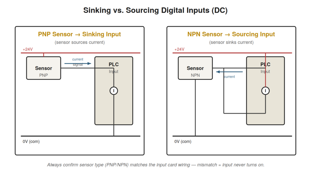
Most modern DC inputs and sensors are described as sinking (NPN) or
sourcing (PNP), and mismatching them is one of the most common wiring
faults. The terms describe the direction of current flow. A sourcing
(PNP) sensor provides the positive voltage to the input when active; a
sinking (NPN) sensor provides the path to common. The input card must be
wired for the type of sensor you are using. If a sensor and input are
mismatched, the input may never turn on, may sit half-on, or may behave
erratically.
sources current into a sinking input; an NPN sensor sinks current from a
sourcing input. The sensor type must match the input card’s wiring
convention.
A reliable procedure for a dead digital input
Actuate the field device and watch the channel LED. If it
follows, the input hardware is fine — the problem is in logic; go
online.If the LED does not follow, measure the voltage at the input
terminal with respect to its common while the device is actuated. You
should see roughly the input’s rated voltage (e.g. 24 V DC).No voltage at the terminal? Work back toward the device: check
the field wiring, the device’s own power, and the sensor output with a
meter.Voltage present but LED and image both off? Suspect the input
channel itself — try a spare channel to confirm.Correct voltage and LED on, but the tag in software is off?
Confirm you are looking at the right tag/address and that the input is
not being forced.
COMMON TRAPA sensor that reads correct voltage unloaded but collapses under the |
Understanding the input circuit
To troubleshoot digital inputs confidently, picture what the input
circuit actually needs to see. A DC input point is looking for a voltage
between its terminal and its common that exceeds a threshold — energize
it above that threshold and the input reads on; drop below and it reads
off. Everything about digital input troubleshooting reduces to one
question: is the correct voltage appearing at the terminal when it
should, and only when it should? The field device, its power, the
wiring, and the sink/source convention all exist to deliver that voltage
correctly.
This framing also explains the confusing middle states. An input that
flickers, or reads on faintly, or responds sluggishly usually has a
voltage that is present but marginal — a high-resistance connection
dropping some of it, a shared common carrying too much, or leakage
current from a solid-state sensor’s output that is enough to partly
energize the input even when the sensor is ‘off.’ Leakage is a real and
underappreciated cause: some two-wire sensors and solid-state outputs
pass a small current even when off, and on a sensitive input that
trickle can be read as an on state. When an input will not turn fully
off, suspect leakage and consider whether a bleeder resistor is
specified.
Grouped commons and the shared-fault trap
Input modules usually group several points onto a shared common. This
matters when you troubleshoot because a fault in that shared common
affects every input in the group at once. If a whole block of inputs
goes dead together while other blocks are fine, do not chase each device
— suspect the common they share. A single loose or broken common
connection can take out eight or sixteen inputs simultaneously, and
chasing them one by one is a long road to a fault that a moment’s
thought about the shared common would have found immediately.
A fuller dead-input walkthrough
Suppose a limit switch that signals ‘gate closed’ is not registering,
and the machine will not proceed. You actuate the gate and watch the
input’s channel LED — it stays dark. That immediately tells you the
problem is on the field side of the input, not in the logic, because the
input hardware is not even seeing the signal. You meter from the input
terminal to its common while the gate is closed and read zero volts,
confirming the signal is not arriving. Now you work backward: at the
switch, is there voltage on the supply side? Yes. Does the switch pass
that voltage through when the gate closes? You meter across the switch —
it stays open even when the gate is fully closed. The switch, or its
mechanical actuation, is the fault. Perhaps the actuator arm is bent, or
the switch has failed. Either way, six measurements have taken you from
a stopped machine to a specific failed component, with no guessing and
no parts thrown at the problem.
AC INPUTS DIFFERMuch of this chapter assumes DC inputs, which dominate modern |
A case file: the input that would not turn off
A proximity sensor’s input reads on constantly, even with no target
present, so the machine thinks a part is always in position. Metering
the input terminal with the target removed shows a few volts present
when it should be near zero — not the full 24 V of a true on, but enough
to hold the input above its threshold. This partial voltage is the
signature of leakage current. The sensor is a three-wire solid-state
type whose output passes a small leakage current even when off, and on
this particular input that trickle is enough to register as on. The fix
is a bleeder resistor across the input to give that leakage somewhere to
go, dropping the off-state voltage safely below threshold. The broader
lesson: an input stuck on with a partial voltage present is often
leakage, not a true signal, and the cure is to bleed off the leakage
rather than to replace a sensor that is working as designed.
Signal timing and fast events
Occasionally a digital input problem is really a timing problem.
Recall that the controller samples inputs once per scan, so a signal
present for less time than one scan can be missed entirely — the input
pulses on and off in the gap between two snapshots, and the logic never
sees it. This shows up with fast events: a high-speed part passing a
sensor, a brief contact closure, a quick pulse from a metering device.
If a machine intermittently misses counts or events that you can confirm
are physically happening, and the signal is genuinely brief, ordinary
scanned inputs may simply be too slow. The remedy is a high-speed input
designed to catch pulses shorter than the scan, or a latching
arrangement that holds the brief signal long enough for the scan to see
it. Recognizing that the fault is timing rather than a broken signal is
what points you toward the right fix.
Wiring conventions and the documentation that saves
you
Digital input troubleshooting is far faster when you can trust the
machine’s documentation, and understanding how that documentation is
organized helps you use it. Electrical drawings show each input’s
terminal, the field device connected to it, and the wire numbers between
them, so that a signal in the program can be traced through the drawing
to a physical terminal and a specific device. When an input is faulty,
the drawing tells you exactly which terminal to meter and which device
to inspect, turning what would be a hunt into a direct lookup. Wire
numbers printed on the drawing and ideally on the wires themselves let
you follow a specific conductor through a panel full of wires. Where
documentation is good, an input fault is a matter of reading the drawing
to find the terminal and device, then verifying them; where it is poor
or out of date, the same work is harder and the discipline of verifying
the actual wiring against whatever drawing exists becomes essential,
because acting on a drawing that no longer matches the machine leads you
confidently to the wrong place.
A case file: the shared-common dropout
Half the inputs on a module stop working simultaneously while the
other half remain fine, and the machine faults on several conditions at
once. The simultaneity is the entire clue: several inputs failing
together, especially a contiguous group, points not at several
coincidental device failures but at something those inputs share. Input
modules commonly group points onto shared commons, and the failed inputs
turn out to be exactly the group sharing one common. Metering reveals
that common has lost its connection — a single loose terminal on the
shared common return, opening the return path for every input in its
group at once. Restoring that one connection revives all the affected
inputs together. The lesson is to read a pattern of simultaneous input
failures as a pointer to a shared element — a common, a shared supply, a
shared module — rather than as a coincidence of individual failures,
because chasing each input separately when they share a single failed
common is a long detour around a fault that the pattern itself
identifies.
A structured summary of digital input faults
Pulling the digital input material together, the faults sort into a
small number of categories that between them cover almost everything you
will meet. There are supply problems, where the field device or the
input circuit lacks the power it needs, from a lost supply, a tripped
protective device, or a sagging voltage that reads fine unloaded. There
are wiring problems, where the connection between device and input is
broken, loose, or high-resistance, including the shared-common faults
that take out a group of inputs at once. There are device problems,
where the field device itself — a switch, a sensor — has failed or
drifted so it no longer produces the signal. There are convention
problems, where a sink/source mismatch prevents the signal from
registering. There are leakage problems, where a solid-state device
passes enough off-state current to hold an input on. And there are
logic-side confusions, where the input hardware is fine but the signal
is not what the machine needs. Recognizing which category a fault falls
into — often from the single question of whether the channel LED follows
the field device — points immediately at the right set of checks, and
this categorization is what turns the individual techniques in this
chapter into a fast, organized approach to any dead or misbehaving
digital input.