Outputs are where the controller acts on the world — energizing a
solenoid, closing a contactor, lighting a lamp. When an output does not
do its job, the question is always the same: is the controller
commanding the output, and if so, is the command reaching the load?
Those two halves split cleanly, and the channel LED plus a meter answer
both.
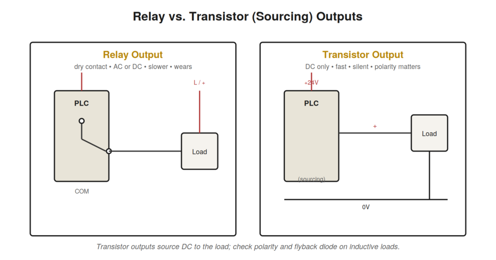
Relay versus transistor outputs
Two output technologies dominate, and knowing which you have changes
how you troubleshoot. Relay outputs are dry mechanical contacts: they
switch AC or DC, tolerate a range of voltages, but are slower and wear
out. Transistor outputs (sourcing or sinking) switch DC only, are fast
and silent, but are polarity-sensitive and intolerant of overload. A
relay output that has switched millions of cycles can develop high
contact resistance or weld closed; a transistor output can fail from an
over-current or an inductive spike.
contacts are voltage-agnostic dry contacts; transistor outputs source DC
to the load and are polarity-sensitive.
A procedure for a dead output
Go online or watch the channel LED: is the controller commanding
the output on? If the LED is off when it should be on, the problem is in
logic — find what the rung is waiting for.If the output LED is on but the load does nothing, the command is
present; the break is downstream.Check the output fuse (many cards or field circuits have one) and
the field wiring for continuity.Measure the voltage across the load while commanded on. Full
voltage present but no action means the load itself has failed; no
voltage means the output device or wiring is open.For a suspected welded relay output, look for an output that will
not turn off — the load stays energized regardless of command.
INDUCTIVE LOADSSolenoids, relays, and contactor coils are inductive. Switching them |
Command versus delivery: the fundamental split
Every output fault resolves into one of two questions, and keeping
them separate is the whole discipline. First: is the controller
commanding the output on? This is a logic question, answered by going
online or watching the channel LED. Second: if commanded, is the command
reaching and driving the load? This is a field question, answered with a
meter at the load. Confuse these and you waste time; separate them and
every output fault becomes tractable. A commanded output with a dead
load is a delivery problem — fuse, wiring, load, or output device. An
uncommanded output that should be on is a logic problem — go find what
the rung is waiting for. The channel LED, which shows what the
controller is commanding, is the pivot between the two questions.
A case file: the intermittent valve
A solenoid valve occasionally fails to actuate, stalling the machine
until someone cycles it. Online, at the moment of failure, the output is
commanded on and the channel LED is lit — so the controller is doing its
job and the fault is downstream. Metering across the solenoid coil
during a failure shows full voltage present, yet the valve does not
shift. Voltage at the coil with no action points past the electrical
path entirely, to the coil or the mechanics. With power isolated, a
resistance check of the coil reveals it is intermittently open — a
failing coil that conducts when cool and opens as it heats. The fix is a
new coil, but the reasoning is what matters: by splitting command from
delivery and then metering at the load, the technician proved the
controller and wiring innocent and localized the fault to the coil
without guesswork.
Fuses, and why they blow
Many output circuits are fused, and a blown output fuse is a common,
quick find — but replacing it without asking why it blew is a mistake. A
fuse blows because current exceeded its rating, and that usually means
something downstream is drawing too much: a shorted wire, a failed load,
or a load too large for the circuit. Replace the fuse and it may blow
again immediately, or worse, damage the output. So when you find a blown
output fuse, look for the cause before replacing it: inspect the wiring
for shorts, check the load, and consider whether the circuit was
recently changed. A fuse is a symptom as much as a component.
Inductive loads and back-EMF in practice
Inductive loads — solenoids, contactor coils, relays, motor brakes —
store energy in a magnetic field, and when the output switches them off
that energy must go somewhere. It appears as a sharp voltage spike of
opposite polarity, the back-EMF, and it can be many times the supply
voltage for an instant. On a relay output this spike erodes the contacts
over time; on a transistor output it can destroy the switching device
outright. Protection is a flyback diode across DC loads or a snubber
across AC loads, placed at or near the load. When you see repeated
failures of the same output, or contacts that wear far faster than
expected, check for missing or failed suppression. Adding proper
suppression is often the difference between an output that lasts years
and one that fails monthly.
A case file: the output that failed monthly
A transistor output driving a solenoid valve fails roughly once a
month, each time replaced, each time failing again — an expensive,
recurring defeat. The repetition itself is the clue: a component that
fails on a regular schedule is being stressed by something in the
circuit, not suffering random bad luck. The solenoid is an inductive
load, and inspection reveals no flyback diode across it. Every time the
output switched the solenoid off, the coil’s collapsing field produced a
back-EMF spike that the transistor output absorbed, and month by month
those spikes degraded it until it failed. Adding the specified flyback
diode across the solenoid gives the spike a safe path, and the output
stops failing. The principle is essential: a repeatedly failing output,
especially a transistor output driving a coil or solenoid, is usually
being killed by an inductive spike from missing or failed suppression.
Fix the suppression and you fix the recurring failure at its root
instead of feeding it new output modules.
Load-side faults versus output faults
When an output does not produce its effect, the fault can lie in the
output itself or entirely in the load, and one measurement usually
distinguishes them. With the output commanded on, meter across the load.
Full rated voltage present across the load means the output and wiring
are delivering power correctly — so if the load still does nothing, the
load itself has failed: a burned-out lamp, an open solenoid coil, a
failed heater. No voltage across the load when commanded means the
delivery path is broken — the output device, a fuse, or the wiring — and
the load may be perfectly good. This single measurement across the load,
taken while commanded on, cleaves the ambiguity:
voltage-present-but-dead points at the load, voltage-absent points at
everything upstream of it. It saves you from replacing a good output
because the load failed, or a good load because the output failed.
Output cards, fuses, and protection
Understanding how output cards protect themselves and their loads
helps you interpret output faults correctly. Many output cards include
fusing, sometimes per group of outputs and sometimes per point, and this
fusing shapes the fault patterns you will see. A blown group fuse takes
out all the outputs in its group together, so a set of outputs failing
simultaneously points at their shared fuse rather than at each output —
the same shared-element logic that governs input commons. An
individually fused output that fails alone points at its own fuse or
output device. Reading whether outputs fail alone or in groups, and
knowing the card’s fusing arrangement, tells you where to look. And as
always with a blown fuse, the fuse is a symptom: it blew because current
exceeded its rating, so replacing it without finding why invites an
immediate repeat or worse. A group of outputs suddenly dead together
should send you to their shared fuse and then to the cause of the
overcurrent that opened it, not to a theory of simultaneous multiple
output failures.
A case file: the welded contact
A relay output controlling a heating element will not turn off — the
heater stays energized regardless of the controller’s command, which is
both a process problem and a safety concern. An output that cannot be
turned off is a distinctive fault pointing at the output device having
failed in the closed state, most commonly a relay whose contacts have
welded together. Metering confirms the load stays energized even when
the controller commands the output off and the channel indicator shows
off, proving the command is correct but the relay contact is stuck
closed. The relay has switched enough high-current cycles that its
contacts finally welded, a known end-of-life failure for relay outputs
driving substantial loads. Replacing the output restores control. The
diagnostic signature is worth remembering: a load that will not turn
off, with the controller correctly commanding off, indicates the output
device is stuck closed rather than any logic problem, and for a relay
output driving a heavy or frequently switched load, a welded contact is
the usual cause. This failure also carries a safety dimension, since an
output that cannot be commanded off defeats the controller’s ability to
stop the load, which is why such a fault warrants prompt attention
rather than a workaround.
A structured summary of digital output faults
The digital output faults resolve, like the inputs, into categories
organized around one pivotal question: is the controller commanding the
output, and if so, is the command reaching the load? Command-side
faults, where the output is not commanded when it should be, are logic
problems — the rung is waiting on an unmet condition — and send you
online to find what the logic needs. Delivery-side faults, where the
output is commanded but the load does not act, subdivide into the output
device itself failing (a blown transistor, a welded or high-resistance
relay contact), protective devices operating (a blown fuse, itself a
symptom of downstream overcurrent), wiring faults (an open or
high-resistance connection between output and load), and load failures
(the solenoid, lamp, or coil itself burned out or open). The decisive
measurement is voltage across the load while commanded on: full voltage
with no action indicts the load, no voltage indicts everything upstream
of it. Two distinctive signatures round out the picture: an output that
will not turn off indicts the output device stuck closed (a welded
relay), and an output that repeatedly fails indicts missing suppression
on an inductive load killing it with back-EMF. Sorting an output fault
into command-side or delivery-side with the channel LED, then localizing
delivery-side faults with a measurement across the load, organizes every
output investigation into a fast, directed sequence.
A case file: the output that worked until it got
warm
An output driving a load works reliably when the machine first starts
but begins to fail after the machine has run for a while and the panel
has warmed up, recovering after the machine cools down overnight. The
correlation with temperature — reliable when cool, failing when warm —
points at a thermal fault, a connection or component whose behavior
changes as it heats. Following this thermal lead, the technician finds a
marginal connection in the output circuit that has enough resistance to
matter, and as the panel heats and the connection’s resistance rises
further with temperature, it eventually degrades the output enough to
fail; cooling overnight restores it. This kind of temperature-dependent
intermittent fault is maddening to catch because it only appears after
the machine has run long enough to warm up, precisely when a technician
who arrives at a fresh fault finds everything working as the panel cools
during the investigation. The pattern itself — reliable cold, failing
warm, recovering after cooling — is the key that identifies a thermal
cause, usually a marginal connection whose resistance climbs with
temperature until it fails. Finding and remaking that connection solidly
eliminates the temperature dependence. The case reinforces a general
principle for intermittent faults: a fault that correlates with the
machine warming up points at a thermally sensitive marginal connection
or component, and the correlation with temperature, visible in when the
fault appears, is what directs the search toward the thermal cause that
a cold inspection would never reveal.