Between the power that does the work and the person or logic that decides when it happens sits the control circuit. Control circuits operate at lower power — often a separate control voltage — and they are where a large share of industrial faults live, because they contain the most components and connections. Understanding how they work makes them far less mysterious to troubleshoot.
Control power and relay logic
A control circuit is usually fed by a control transformer that provides a lower, safer voltage — commonly 120 V in North America or 24 V or 230 V in various installations — separate from the motor power. Within the control circuit, the logic is built from contacts and coils: a coil, when energized, operates its contacts, which in turn control other coils or loads. This relay logic, whether built from physical relays or represented in a PLC, is what turns a start button and a set of conditions into a running motor. Reading it means following which contacts must close for a given coil to energize.
Start, stop, and seal-in
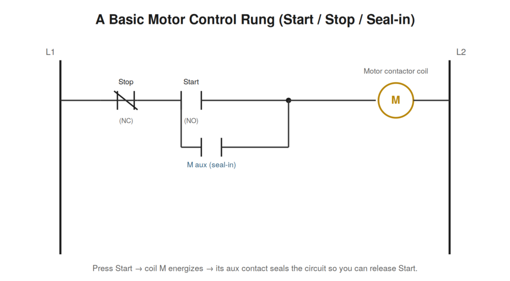
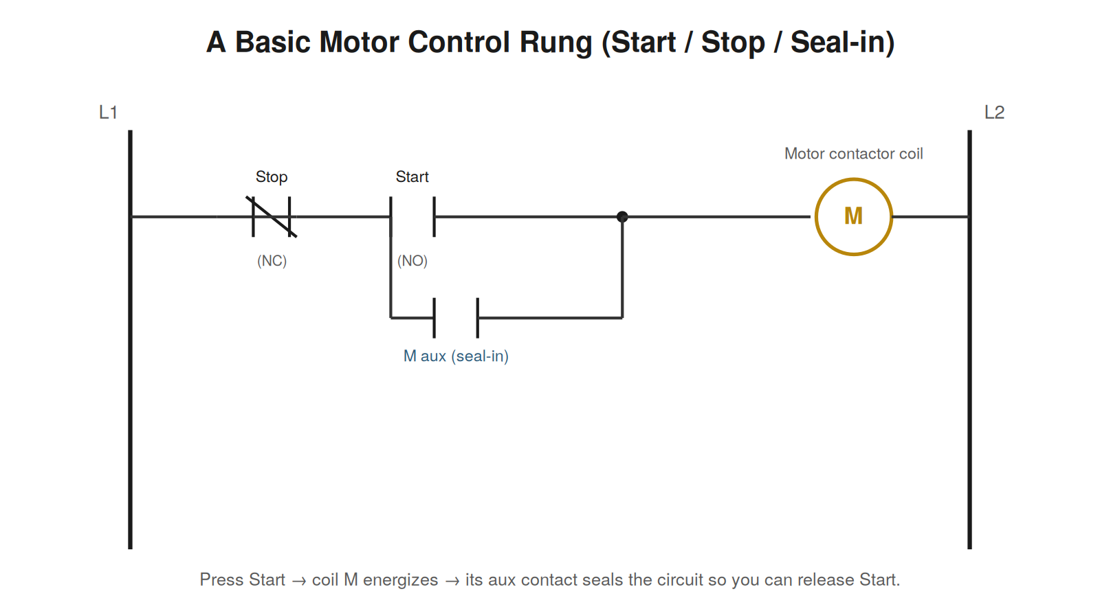
The classic control circuit is the start/stop/seal-in arrangement that runs most motors. A normally-open start button and a normally-closed stop button control a contactor coil. Pressing start energizes the coil, which closes the main contacts to run the motor — but a start button is momentary, so the circuit needs a way to keep the coil energized after the button is released. That job falls to the seal-in: an auxiliary contact on the contactor itself, wired in parallel with the start button, which closes when the coil energizes and holds the circuit closed. Pressing stop, or an overload opening, breaks the coil circuit and drops everything out. Recognizing this pattern lets you troubleshoot a huge fraction of motor control faults, because you can reason about exactly which element — start, stop, seal-in, coil, or overload — is preventing the coil from energizing or holding.
Permissives and interlocks
Real control circuits add conditions beyond start and stop: permissives that must be satisfied before an action is allowed, and interlocks that prevent unsafe or conflicting operations. A guard must be closed, a previous step must be complete, a pressure must be adequate, two conflicting motions must not run at once. When a machine ‘refuses’ to operate, it is very often not broken but correctly withholding operation because a permissive is not met. Reading the control circuit reveals which condition is missing, and that missing condition frequently points straight at the real fault — a failed limit switch reporting a guard open, a pressure switch that has not made, a prior step that did not complete. Do not fight the interlock; find why its condition is not satisfied.
A COMMON TRAPA control circuit fault and a power circuit fault produce the same symptom — the motor does not run — but live in different places. Determining early whether the contactor coil is even energizing splits these two worlds and saves you from checking motor power when the fault is a control wire, or vice versa. |
A case file: the motor that would not seal in
An operator reports that a motor runs only while the start button is held down and stops the instant it is released. This very specific symptom points directly at the seal-in circuit, because the seal-in is exactly what holds the coil energized after the start button is released. The motor starts, proving the coil, the contactor, and the motor power are all fine; it drops out on release, proving the seal-in is not holding. Reading the control circuit, the technician follows the seal-in path — the auxiliary contact on the contactor wired in parallel with the start button — and finds a broken wire in that branch. With the seal-in branch open, pressing start energizes the coil through the start button, but releasing start removes the only path holding the coil, so it drops out. Repairing the seal-in wire restores normal operation. The symptom named the fault: a motor that runs only while start is held has a seal-in problem, and the control drawing leads straight to the seal-in branch to find the specific break.
Separating control faults from power faults
Because a control fault and a power fault produce the same visible symptom — the motor does not run — the most valuable early move in motor troubleshooting is to determine which world the fault lives in. The dividing question is whether the contactor coil is energizing and the contactor pulling in. If the coil is not energizing, the fault is in the control circuit: the start/stop/seal-in logic, a permissive, a control wire, the coil itself. If the coil is energizing and the contactor pulling in but the motor still does not run, the fault is in the power circuit: the main contacts, the motor power wiring, or the motor. This single split saves enormous time, because it directs you either to the control circuit or to the power circuit rather than searching both. Listening and looking for the contactor to pull in, or metering the coil, answers the question in seconds and cleaves the fault space in half.
Reading a sequence of operations
Many machines operate as sequences — a series of steps executed in order, each waiting for its conditions before advancing — and understanding this structure helps enormously when a machine stops partway through its cycle. A machine stuck mid-sequence is waiting for a specific condition to advance from one step to the next, and identifying that condition identifies the fault. When a machine halts partway through, the question becomes which step it is on and what that step is waiting for. A step waiting for a position to be reached, a pressure to build, a previous motion to complete, or a permissive to be satisfied is a step whose advance condition is not met, and that unmet condition is the fault, named by the machine’s own sequence logic. Machines that stop cleanly at a consistent point in their cycle are almost always waiting on a specific step’s advance condition rather than suffering a random failure, and reading the control logic to find which condition is missing points directly at the device or signal responsible.
Control transformers and control power faults
The control circuit’s own power supply — often a control transformer stepping the line voltage down to a lower control voltage — is a point of failure worth understanding, because a control power problem disables the entire control circuit while leaving the main power intact. If the control transformer fails, or its protection opens, or its supply is lost, no control circuit can operate even though the main power to the equipment is present, producing a machine that is fully powered yet completely unresponsive. Checking that the control voltage is present is therefore an early step when a machine will not respond at all, because its absence explains a total lack of control response and points at the control transformer, its fusing, or its supply rather than at any individual control component. A control circuit fault localized to the control power affects everything downstream at once, and recognizing that a machine with main power but no control response likely has a control power problem saves searching the individual control components for a fault that lies in their common supply.
A case file: the permissive nobody suspected
A machine will not start, and everything in the obvious start circuit checks out — the start button works, the stop circuit is intact, the contactor and coil are healthy. Yet the coil will not energize when start is pressed. Reading the full control circuit rather than just the start/stop portion, the technician finds a permissive contact wired into the circuit that nobody had been thinking about: a contact from a lubrication pressure switch that must be satisfied before the main drive is allowed to start, protecting the machine from running without lubrication. The lubrication pressure had not built up — a separate problem with the lube system — so the permissive was correctly holding the main drive off. The machine was not faulty in its start circuit at all; it was correctly refusing to start because a protective permissive was not satisfied, and the real fault lay in the lubrication system that was failing to build pressure. The case illustrates that when a machine will not operate and the obvious start circuit is healthy, a permissive or interlock is often correctly withholding operation because its condition is not met, and reading the full control circuit to find the unsatisfied condition points at the real fault — here, a lube system problem — that the permissive was designed to guard against. Do not fight the interlock; find why its condition is not satisfied.
Control circuits as the home of most faults
There is a reason so much troubleshooting attention goes to control circuits: they contain the most components and connections, and so they are where a large share of faults live. A power circuit may be relatively simple — a supply, a switching device, a load — while the control circuit that governs it can contain dozens of contacts, coils, buttons, switches, permissives, and interlocks, each with its wiring and terminations, any of which can fail. This density of components and connections makes the control circuit statistically the most likely place for a fault, and it means that understanding control logic — how contacts and coils combine to produce actions, how start/stop/seal-in holds a motor, how permissives and interlocks withhold operation until conditions are met — pays off constantly. The troubleshooter who reads control circuits fluently can reason about exactly which element is preventing an action and go test it, while one who finds control circuits mysterious is reduced to guessing among their many components. Because control circuits are both where most faults live and where fluent reading most sharply separates fast troubleshooting from slow, the effort to become comfortable reading them is among the highest-return investments a troubleshooter can make, turning the most fault-prone part of the system from a source of mystery into a readable logic that points at its own faults.
A case file: the machine stuck mid-cycle
A machine that runs as a sequence of steps halts partway through its cycle, stopping cleanly at the same point every time. The consistency of the stopping point is the key: a machine that stops randomly might have an intermittent fault, but one that halts reliably at the same step is waiting for that step’s advance condition, which is not being met. Reading the control logic to find what the stuck step requires to advance, the technician identifies the condition — a position that must be reached and confirmed by a limit switch before the sequence proceeds — and finds that the limit switch is not making, so the sequence correctly waits at that step forever. The machine is not broken in the sense of a component failing randomly; it is correctly stalled because a step’s advance condition is genuinely unmet, and the real fault is the limit switch that is failing to confirm the position. Investigating the limit switch reveals it out of adjustment, no longer actuated by the mechanism at the position it should confirm. The case demonstrates that a machine halting reliably at a consistent point in its cycle is almost always waiting on that step’s advance condition rather than suffering a random failure, and that reading the sequence logic to find which condition is unmet points directly at the device — here a misadjusted limit switch — responsible for the stall. The machine’s own sequence logic, read at the point where it stops, names the condition it is waiting for and thus the fault.
Tracing a control fault to its element
When a control circuit fails to produce an action, the systematic approach is to trace through the logic to the specific element preventing it, and the start/stop/seal-in pattern illustrates the method that generalizes to any control circuit. The output that will not operate — a coil that will not energize — is controlled by a chain of conditions, and each condition is a place to check. For a motor that will not start, the chain is: is the stop circuit intact (its normally-closed contacts closed), is the start actually making contact when pressed, is the seal-in path available, are any permissives and interlocks satisfied, and does the coil itself respond when its circuit is complete? Checking these conditions in turn — reading the control circuit to know what they are, then verifying each — localizes the fault to the specific element that is failing to satisfy its condition. This tracing method generalizes: any control output that will not operate is held off by some unsatisfied condition in the logic that controls it, and reading that logic to enumerate the conditions, then checking each, finds the one that is not met and thus the fault. The power of the approach is that it replaces guessing among a control circuit’s many components with a directed check of exactly the conditions that must be true for the failed output to operate, turning the control circuit’s own logic into a map that leads to its fault. Combined with the earlier split — determining first whether the fault is in the control circuit or the power circuit by checking whether the coil energizes — this tracing method resolves the great majority of control faults efficiently.