Variable frequency drives (VFDs) control motor speed by converting the incoming AC to DC and then synthesizing a variable-frequency AC output. They are everywhere in modern industry, and while they are sophisticated, their faults are diagnosable with a clear method — helped enormously by the fact that drives report their own faults.
How a drive works, briefly
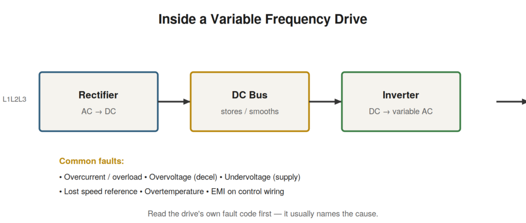
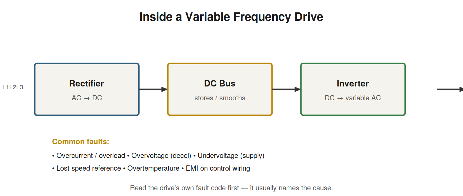
A VFD has three main stages. The rectifier converts the incoming AC supply to DC. The DC bus, with its capacitors, smooths and stores that DC. The inverter switches the DC to produce an output of variable voltage and frequency, which controls the motor’s speed and torque. Understanding these stages localizes drive faults: a supply problem shows at the rectifier and DC bus, an output or motor problem shows at the inverter, and the DC bus voltage is a key health indicator throughout. The drive also has a control section that takes speed references and run commands and manages protection.
Reading the drive’s own diagnostics
The most powerful feature for troubleshooting a drive is that it monitors itself and reports faults by code. A drive fault code names what the drive detected — an overcurrent, an overvoltage, an undervoltage, an overtemperature, a lost reference, a ground fault, a communication loss — and points at the cause far more directly than treating the drive as a black box. When a driven axis misbehaves, read the drive’s fault before assuming anything, because the drive sits closest to the motor and often detects the real problem first. An overcurrent fault points toward the motor or a mechanical overload; an overvoltage fault often relates to rapid deceleration or a supply issue; an undervoltage fault points at the incoming supply; a lost-reference fault points back at the control signal.
References, run commands, and parameters
A drive needs both a run command and a speed reference to operate, and confusing the two causes real trouble. A drive can have a perfect speed reference and still sit idle because the run command is missing, which looks like a reference fault but is not. When a drive will not run, confirm both the run command and the speed reference before diving deep into either. Beyond signals, drives have extensive parameters that configure their behavior, and a wrong parameter — an incorrect speed limit, a miswired reference scaling, a protection setting — can produce faults that look like hardware problems but are configuration errors. After a drive is replaced or its parameters are changed, a parameter mismatch is a common and easily overlooked cause of misbehavior.
Electrical noise and drives
Drives are powerful sources of electrical noise because they switch high currents rapidly, and this noise can disrupt both the drive’s own control signals and nearby sensitive equipment. Control and signal wiring routed too close to a drive’s output cables can pick up interference that causes erratic behavior, and a drive’s output cabling radiates noise that can affect analog signals and communications elsewhere. Proper installation practices — shielded motor cables, careful routing that separates power from signal, and good grounding — prevent most of these problems, and when erratic faults appear around drives, noise from routing and grounding is a prime suspect. A fault that appears only when a nearby drive runs is very often a noise-coupling problem rather than a fault in the affected equipment itself.
A case file: the drive that faulted on deceleration
A drive runs fine until the machine decelerates quickly, at which point it faults on overvoltage and stops. The correlation with deceleration is the clue, and it points at a well-understood drive behavior: when a drive decelerates a motor quickly, the motor acts as a generator, feeding energy back into the drive’s DC bus and pushing its voltage up, and if that voltage rises too high the drive trips on overvoltage to protect itself. The fault is not a component failure but a mismatch between the deceleration rate demanded and the drive’s ability to absorb the returned energy. The solutions are known: extending the deceleration time so the energy returns more gradually, or adding a braking resistor or unit to absorb the returned energy, allowing fast deceleration without the voltage rising too far. Reading the drive’s own overvoltage fault code and noticing it coincides with deceleration leads directly to this understanding, whereas treating the drive as a mysterious black box would leave the technician replacing healthy hardware. The drive’s fault code, correlated with what the machine was doing, named the cause.
Parameters, references, and the two-part run requirement
A large share of drive problems that look like faults are really configuration issues, and two areas dominate. First, the two-part run requirement: a drive needs both a run command and a speed reference, and a drive with a perfect reference sitting idle for want of a run command looks like a reference fault but is not, so both must be confirmed whenever a drive will not run. Second, parameters: a drive’s behavior is shaped by many parameter settings, and a wrong one — an incorrect speed limit, a miswired reference scaling, an inappropriate protection setting, an acceleration or deceleration rate that provokes faults — produces misbehavior that mimics hardware failure. After a drive is replaced or its parameters are changed, a parameter mismatch is among the most common and most overlooked causes of trouble, because the hardware is sound and only the configuration is wrong. Checking that the run command and reference are both present, and that the parameters match what the application requires, resolves many drive faults without touching the hardware at all.
A structured approach to drive faults
Drive troubleshooting becomes systematic when anchored on the drive’s own fault reporting and its internal stages. The first move is always to read the drive’s fault code, because the drive monitors itself and its code names what it detected, pointing at the cause far more directly than treating the drive as a black box. From the code, the investigation follows to the relevant stage: an overcurrent points toward the motor or a mechanical overload on the output side, an overvoltage often relates to rapid deceleration returning energy to the DC bus or to a supply issue, an undervoltage points at the incoming supply, an overtemperature points at cooling or ambient conditions, a lost reference points back at the control signal, and a ground fault points at the motor or its cable. Alongside the code, the two-part run requirement — both a run command and a speed reference must be present — and the parameter set must be checked, because a large share of drive problems are configuration issues rather than hardware failures. This structure — read the code, follow it to the stage, confirm command and reference, check parameters — resolves most drive faults without treating the drive as mysterious, because the drive itself has usually already identified the problem and only needs to be listened to.
A case file: the drive undone by noise
A drive-controlled system behaves erratically — occasional faults, unstable operation — and no fault can be found in the drive hardware or the motor, both of which test healthy. The breakthrough comes from noticing that the erratic behavior involves the drive’s control signals, and that the control wiring runs alongside the drive’s output cables to the motor. Drives switch high currents rapidly and are powerful sources of electrical noise, and the drive’s output cabling was radiating interference into the control wiring routed too close to it, corrupting the control signals and producing the erratic behavior. Neither the drive nor the motor was faulty; the fault was noise coupling from the output cables into the control wiring because of how the wiring was routed. Separating the control wiring from the output cables, using shielded cable and proper grounding, resolves the problem. The case demonstrates a fault class specific to drives: erratic behavior with no hardware fault found, caused by the drive’s own electrical noise coupling into nearby signal or control wiring routed too close to its output. When a drive system misbehaves erratically and the hardware tests healthy, noise coupling from the drive’s output — a routing and shielding problem rather than a component fault — is a prime suspect, and the fix lies in the installation practices that keep the drive’s noise out of sensitive wiring.
The drive that diagnoses itself
The single most important habit in drive troubleshooting is to read the drive’s own fault code first, because a modern drive monitors itself extensively and its fault reporting usually identifies the problem more directly than any external investigation could. The drive sits closest to the motor and its power circuit, continuously watching current, voltage, temperature, its DC bus, its control signals, and more, and when something goes wrong it records a fault code naming what it detected. Treating the drive as a mysterious black box and investigating around it wastes the diagnosis the drive has already performed, while reading its code turns the drive into the most informed witness to the fault. An overcurrent code directs attention to the motor or a mechanical overload; an overvoltage code points at deceleration or supply; an undervoltage code at the incoming supply; an overtemperature code at cooling or ambient; a lost-reference code at the control signal; a ground-fault code at the motor or its cable. In each case the drive has narrowed the problem before the technician begins, and the efficient approach is to start from the code and follow it to the indicated stage rather than to investigate the whole drive system blindly. The drive that diagnoses itself is one of the most helpful features in modern industrial equipment, and listening to it — reading the code first, every time — is the habit that makes drive troubleshooting systematic rather than mysterious.
Configuration versus hardware faults
A theme worth emphasizing in drive troubleshooting is that a large share of drive problems are configuration issues rather than hardware failures, and recognizing this saves enormous wasted effort replacing healthy drives. A drive’s behavior is governed by many parameters — speed limits, acceleration and deceleration rates, reference scaling and sources, protection settings, control modes — and a wrong parameter produces misbehavior that can look exactly like a hardware fault while the hardware is entirely sound. This is especially common after a drive is replaced or its settings are changed, when a parameter mismatch between what the application requires and what the drive is set to do can cause faults, wrong speeds, failures to run, or erratic operation, none of which any amount of hardware investigation will resolve because the hardware is not at fault. The practical discipline is to consider configuration alongside hardware when a drive misbehaves, particularly to check that the parameters match the application’s requirements after any replacement or change, and to remember the two-part run requirement — both a run command and a speed reference must be present — as a configuration-level cause of a drive sitting idle. A drive that will not run, runs at the wrong speed, or faults in ways that do not correspond to an obvious hardware problem may well be misconfigured rather than broken, and checking the parameters and signals before or alongside investigating the hardware is what distinguishes efficient drive troubleshooting from the wasteful cycle of replacing healthy drives that then misbehave identically because the configuration, not the hardware, was the problem all along. The drive’s sophistication, which makes it powerful, also makes it configurable in ways that create configuration faults, and treating the configuration as a first-class suspect is part of troubleshooting drives well.