Before the symbols for components comes the most basic element of all: the lines that connect them. Lines represent conductors — the wires that carry current between components — and reading how lines connect is as fundamental as reading the symbols they join. Get this wrong and the whole circuit is misread; get it right and the components fall into place.
Lines are conductors
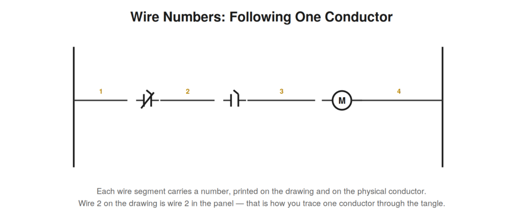
Every line on a schematic is a conductor, and a continuous line means a continuous electrical connection: two points joined by an unbroken line are electrically the same point, at the same potential. This simple fact is the foundation of reading connections. Where lines meet, you must determine whether they actually connect or merely cross without touching, because a junction where two conductors join is electrically very different from two conductors that cross over each other unconnected. Conventions distinguish these: a connection is usually marked with a dot at the junction, while a crossing without connection is drawn without a dot, sometimes with one line hopping over the other. Reading these junctions correctly is essential, because a dot changes the circuit entirely — it joins two conductors into one node.
Nodes: electrically common points
A node is a set of points all connected together by conductors, and therefore all electrically identical. Everything joined by unbroken lines and connection dots forms one node, at one potential, and recognizing nodes is central to reading a circuit. When you trace a line and follow it through every junction it connects to, you are mapping a node — finding every point that is electrically the same. This matters because a measurement anywhere on a node reads the same as anywhere else on it, and because understanding which points form a node tells you how current can flow. Learning to see nodes — to follow a conductor through its junctions and recognize all the points it ties together — is a core reading skill that turns a web of lines into a set of distinct electrical points.
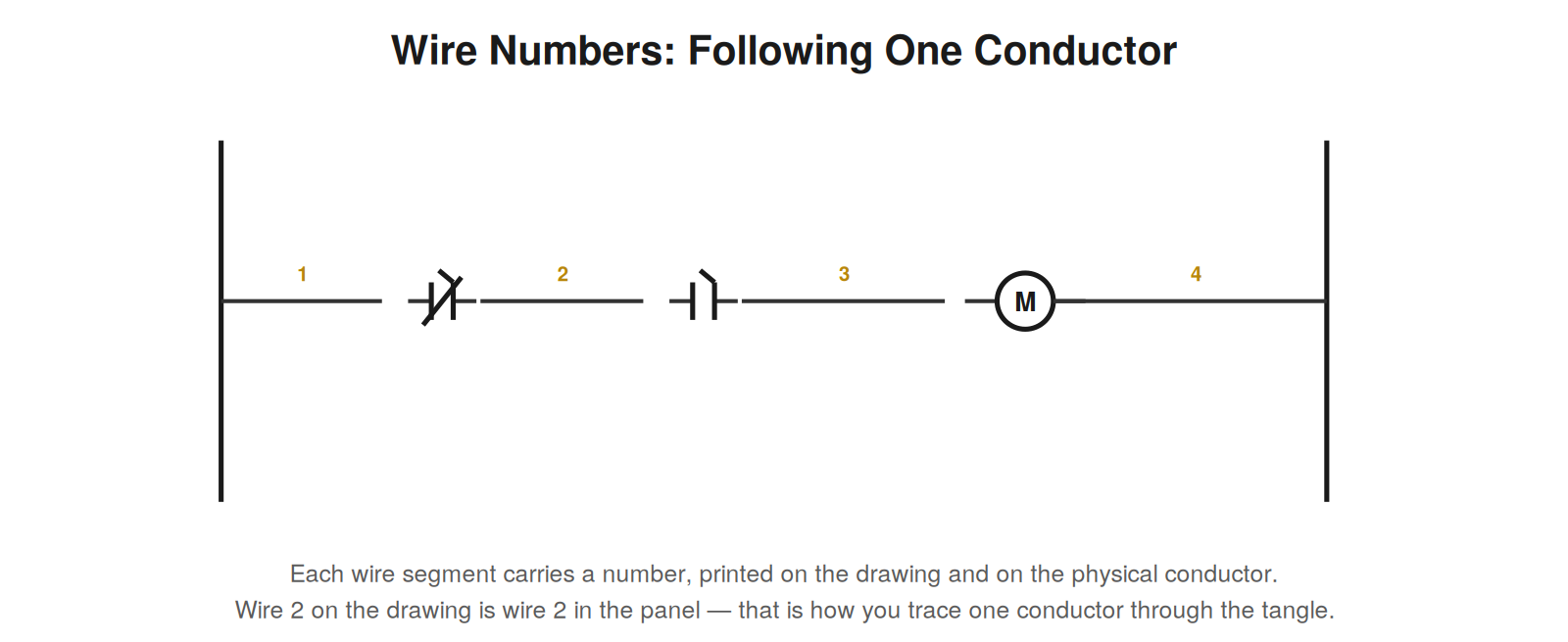
Wire numbering
In any real installation with more than a handful of conductors, wire numbering is what makes a specific wire findable. Each wire segment is assigned a number, printed on the drawing and — in a well-maintained installation — marked on the physical conductor with the same number. This correspondence is invaluable: a wire identified on the drawing can be found in the panel, and a wire found in the panel can be located on the drawing, simply by matching numbers. When troubleshooting a specific circuit, identifying the relevant wire numbers on the drawing and finding those same numbers in the panel focuses your attention on exactly the right conductors among hundreds. Wire numbering is the practical link between the abstract drawing and the physical wiring, and reading it is what lets you cross between the two.
WHEN NUMBERS CHANGEA wire number typically stays the same along a conductor until it passes through a component that changes it electrically — a contact, for instance. The segment before a contact and the segment after it are different wires with different numbers, because the contact can make or break the connection between them. Watching where numbers change helps you see where the circuit’s nodes begin and end. |
The dot that changes everything
One small mark on a schematic carries enormous weight: the connection dot at a junction of lines. Where two lines cross, they either connect or they do not, and the dot is what distinguishes the two cases — a dot means the conductors join into one node, no dot means they cross without touching. Misreading this single mark inverts the circuit, because a junction that connects three wires into a common node behaves completely differently from three wires that merely cross. Reading junctions carefully — noting where dots are and are not — is therefore fundamental, and it is a common source of reading errors for beginners who overlook the dots. Some drawing conventions reduce the ambiguity by drawing crossing-without-connection as one line hopping over the other in a small arc, reserving plain crossings for connections, but where the dot convention is used, the dot is decisive. Slow down at junctions, read the dots, and you read the nodes correctly; rush past them, and you may misread the entire circuit.
Tracing a node in practice
Tracing a node — following a conductor through all its junctions to find every point electrically common to it — is a practical skill worth practicing deliberately. Pick a point on the drawing and follow its line: at each junction with a connection dot, the node extends to the joined conductor; at each component like a contact, the node ends, because the component can break the connection. By following all the connected segments, you map the node — every point at the same potential. This matters in troubleshooting because a measurement anywhere on a node reads the same, so knowing the extent of a node tells you where you can equivalently measure, and knowing where nodes end (at components) tells you where the interesting electrical action happens. Practicing node tracing on drawings until it is quick builds the foundational skill of seeing a schematic not as a web of lines but as a set of distinct electrical nodes joined by components, which is how the circuit actually behaves and how a fluent reader sees it.
Reading exercise: mapping the nodes of a rung
A powerful exercise for solidifying the node concept is to take a single rung and map its nodes explicitly — marking each distinct electrical point and noting where one node ends and the next begins. Start at the left rail (one node) and move right: the wire up to the first contact is one node; the contact separates it from the next node; the wire between the first and second contacts is another node; and so on to the output and the right rail. Marking these nodes, and noting that each contact is the boundary between two nodes, makes vivid how the rung is a chain of nodes joined by components. This matters because troubleshooting is often about determining which node is energized and which is not — the fault is frequently at the boundary (a component) between an energized node and a dead one. Mapping nodes explicitly on practice rungs builds the habit of seeing the rung as distinct electrical points rather than an undifferentiated line, which is how you reason about where power is present and where it stops.
How wire numbers reveal circuit structure
Wire numbers do more than locate physical conductors; read attentively, they reveal the structure of the circuit itself. Because a wire number typically stays constant along a node and changes across a component, the pattern of wire numbers maps the circuit’s nodes and the components between them. Where a number persists, you have one node; where it changes, a component has intervened. Reading the wire numbers along a rung, you can trace the sequence of nodes and components even before analyzing the logic in detail, using the numbers as a guide to the circuit’s structure. This is a subtle but useful reading technique: the wire numbers, which exist primarily for physical identification, double as markers of the circuit’s electrical structure, and reading them reveals where nodes begin and end. On a complex drawing, following the wire numbers can help you keep track of which node you are on and where components separate one node from the next, adding a layer of structural information to your reading beyond what the lines and symbols alone convey.
Common wire-numbering schemes
Wire-numbering schemes vary, and recognizing the common approaches helps you read the numbers meaningfully rather than as arbitrary labels. Some schemes number wires sequentially throughout a drawing; others encode information in the number, such as the sheet, the circuit, or the function, so the number itself tells you something about the wire. Some tie the wire number to the terminal it connects to, or to the device it serves. Reading the wire numbers with awareness of the scheme in use — often explained in the drawing’s notes — lets you extract whatever information the scheme encodes, beyond mere identification. In a scheme where numbers encode the sheet and circuit, a wire number tells you where in the drawing set the wire belongs; in a scheme tied to terminals, it tells you the terminal. Understanding the scheme turns the wire numbers from opaque labels into informative identifiers, and reading them accordingly adds to your understanding of the circuit’s structure and organization. While you can use any scheme’s numbers for basic identification, reading them with knowledge of the scheme extracts the additional structure they encode, which the drawing’s designers built in to aid exactly the navigation you are doing.
Case: using wire numbers to find a break
A broken or disconnected wire is a common fault, and wire numbers are the tool that locates it efficiently. A circuit was open somewhere — a conductor broken or disconnected — leaving part of the circuit dead. Reading the drawing, the dead portion corresponded to a particular node with a particular wire number, and the live portion to another. The break was between them, where the wire number changed or along the dead node. Using the wire numbers, the technician identified the specific wire that should connect the live portion to the dead portion and checked that wire physically — finding it disconnected at a terminal. Without the wire numbers, locating which of many wires was the broken one would have been slow; with them, the drawing named the wire, and it was found and reconnected quickly. This case shows the practical value of wire numbers for locating opens: the drawing, read with its wire numbers, tells you which specific conductor carries the circuit between the live and dead portions, and that is the wire to check. Reading the wire numbers turned ‘a wire is broken somewhere’ into ‘this specific numbered wire is the one to check,’ which is the difference between a quick fix and a long search through the panel’s many conductors.
The discipline of reading junctions carefully
Among the disciplines that distinguish accurate readers is the care taken at junctions — reading every connection dot correctly and never rushing past a crossing without determining whether it connects. This discipline matters because junctions determine the circuit’s nodes, and a misread junction misreads the circuit’s structure. The pitfall is to skim over junctions, assuming connections or missing dots, which corrupts the reading of the nodes. The discipline is to attend to each junction: is there a dot (connection) or not (crossing)? This attention, applied consistently, ensures the nodes are read correctly, which is foundational to everything else. Developing this discipline means slowing down at junctions until reading them correctly is habitual, then maintaining the care even as reading becomes fast. Accurate readers never rush junctions, because the small dots at junctions carry large consequences for the circuit’s structure. Making the careful reading of junctions a consistent discipline — always determining connection or crossing at each junction — is part of the accuracy that reliable reading requires, and it is a discipline worth cultivating deliberately, because the junctions are small and easy to skim but decisive for reading the nodes correctly, and the nodes are the basis of understanding the circuit.