If any symbols are the heart of industrial schematics, they are the contact and the coil. Together they express control logic — the decisions that turn equipment on and off in response to conditions — and the great majority of control drawings are built from them. Understanding contacts and coils thoroughly is the single most important step in learning to read control schematics.
Normally-open and normally-closed contacts
A contact is an electrical switch that is either open (no connection) or closed (connection made), and it comes in two forms distinguished by their resting state. A normally-open (NO) contact is open at rest and closes when operated — when its controlling coil energizes or its button is pressed. A normally-closed (NC) contact is closed at rest and opens when operated. The two are drawn differently: the NO contact shows a gap, while the NC contact adds a slash across it to indicate its closed-at-rest state. This distinction is critical, because a NO and a NC contact of the same device behave oppositely — when the device operates, the NO closes and the NC opens — and misreading one for the other inverts the logic. Reading the resting state of every contact, NO or NC, is fundamental to reading what a rung does.
Coils and the contacts they control
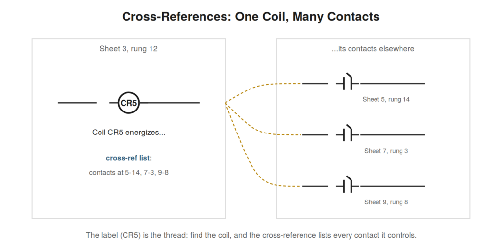
A coil represents the operating element of a relay or contactor — an electromagnet that, when energized, operates all the contacts associated with it. Drawn as a circle (NEC) or rectangle (IEC), the coil is the cause and its contacts are the effect: energize the coil, and every NO contact bearing its label closes while every NC contact bearing its label opens. This is the central mechanism of relay logic. The link between a coil and its contacts is the label: a coil labeled CR5 controls every contact also labeled CR5, wherever they appear in the drawing. Reading control logic means constantly tracing this cause-and-effect — seeing that this coil, when energized, operates those contacts elsewhere, which in turn control other coils and loads. The coil-and-contact relationship, connected by labels, is the grammar of control schematics.

Following the cause and effect
Because a coil’s contacts may be scattered across the drawing, following the cause and effect requires the cross-references introduced earlier. When you see a coil energize, the cross-reference tells you every contact it operates and where they are, so you can follow the consequences through the circuit. Conversely, when you see a contact that matters to a circuit you are reading, you can find its controlling coil and understand what makes it operate. This back-and-forth — from coil to its contacts, from contact to its coil — is how you trace logic through a control drawing, following the chain of causes and effects from an input all the way to an output. Mastering it is mastering the reading of control schematics, because everything else is built on this grammar of coils operating contacts that control other coils.
THE LABEL IS EVERYTHINGTwo contacts drawn identically are completely different if they bear different labels, because different labels mean different controlling devices. Always read the label, not just the shape: the shape tells you the type of contact, but the label tells you what operates it and thus what it means in the circuit. |
A worked example of coil-and-contact logic
Consider a small piece of logic to see coil-and-contact reading in action. Coil CR1 is energized by a start condition on one rung. Elsewhere, a normally-open CR1 contact appears in a second rung that controls a lamp, and a normally-closed CR1 contact appears in a third rung that controls a different output. Reading the cause and effect: when the start condition energizes CR1, its normally-open contact (rung 2) closes, lighting the lamp, while its normally-closed contact (rung 3) opens, removing the other output. One coil, energized, simultaneously turns one thing on and another off, through its two contacts of opposite types. Reading this requires following CR1’s label to both contacts and understanding that energizing the coil operates both — closing the NO, opening the NC. This is the essence of relay logic reading: a coil operates its labeled contacts, of whatever type, wherever they appear, and following the label from coil to contacts reveals the full effect of energizing that coil across the whole circuit.
Why one coil controls many contacts
A single coil often controls several contacts, and understanding why illuminates how relay logic achieves complex behavior from simple elements. A physical relay or contactor has one coil but multiple contacts, all operated together when the coil energizes, and this lets one condition (the coil energizing) simultaneously affect several parts of the circuit. One relay can, when energized, start one thing, stop another, enable a third, and indicate its state on a lamp — all through its several contacts of appropriate types placed in the relevant rungs. Reading this means recognizing that the scattered contacts bearing one label are all operated by that one coil, so energizing the coil has effects everywhere its contacts appear. This one-to-many relationship is how relay logic builds sophisticated coordinated behavior from simple coils and contacts: each coil is a single decision, and its multiple contacts carry that decision to every place it needs to act. Following a coil to all its contacts reveals the full reach of each decision in the logic.
Reading exercise: predicting contact states
A revealing exercise for coil-and-contact fluency is to pick a coil, imagine it energized, and predict the state of every one of its contacts across the drawing. When coil CR1 energizes, every normally-open CR1 contact closes and every normally-closed CR1 contact opens — so go through the drawing, find each CR1 contact, and state its new position. Then imagine CR1 de-energized and predict again: NO contacts open, NC contacts closed. This exercise builds the core skill of following a coil’s effect to all its contacts and understanding how energizing the coil changes the circuit everywhere its contacts appear. It also reinforces reading contact types carefully, since NO and NC respond oppositely to the coil. Practicing this prediction — coil energized, predict all contacts; coil de-energized, predict again — develops the fluency to trace a coil’s effect through the whole circuit at a glance, which is exactly what reading control logic requires as you follow one coil’s contacts into the rungs they control and predict how those rungs respond.
Auxiliary contacts and their role
A refinement worth understanding is the distinction between a contactor’s main contacts, which switch the load’s power, and its auxiliary contacts, which are used in the control logic — because reading them correctly clarifies how control and power link. A contactor has heavy main contacts sized to switch the motor current, and lighter auxiliary contacts used for control functions like the seal-in or for signaling the contactor’s state to other logic. On the drawings, the main contacts appear in the power circuit switching the motor, while the auxiliary contacts appear in control rungs — the seal-in contact, an interlock contact, a contact lighting a run lamp. All are operated by the same coil, but they play different roles: main contacts deliver power, auxiliary contacts participate in logic. Reading them means recognizing which is which by their location and use — main contacts in the power path, auxiliaries in control rungs — and understanding that the single coil operates all of them together. This distinction explains how one contactor both switches the motor’s power and participates in the control logic, through its two kinds of contacts, and reading it correctly is part of following the control-to-power link.
Latching relays and memory in logic
Beyond the momentary coils that de-energize when their rung opens, some relays latch — holding their state until explicitly reset — and reading these requires recognizing that they add memory to the logic. A latching relay, once set, stays set even after the setting condition is removed, until a separate reset condition clears it, which is different from an ordinary coil that follows its rung. On the drawing, latching relays are indicated by their symbols or labels, and reading them means recognizing that they remember a state rather than merely following their input. This matters because a latched relay’s contacts reflect a past event (the set) that persists, not the current state of the setting condition — so reading the logic requires tracking what set the latch and what will reset it. The seal-in circuit achieves a similar memory through the holding contact, but explicit latching relays make the memory a distinct function. Reading logic that includes latching means understanding this persistence — the relay holds its state until reset — which adds the dimension of memory to the logic and requires reading both the set and reset conditions to understand the latched relay’s behavior over time, not just at one instant.
Case: the relay that would not energize
A relay not energizing when it should is a frequent fault, and reading the coil-and-contact logic diagnoses it. A relay’s contacts were not operating, meaning its coil was not energized, and the machine misbehaved as a result. Reading the drawing, the relay’s coil was on a rung with its own conditions, so the coil not energizing meant those conditions were not all satisfied. Reading that rung listed the conditions the coil depended on, and checking them found one unmet — a contact upstream not closing, itself operated by another device. Following the coil-and-contact chain — this coil not energized because its rung’s conditions unmet, one of which is a contact operated by another coil not energized because of its rung’s conditions — led back to the root cause. This case shows reading coil-and-contact logic in troubleshooting: a coil not energizing sends you to read its rung and check its conditions, and where a condition is a contact of another coil, you follow that back too, tracing the chain of coils and contacts to the root. Reading this chain — from the symptom (a relay not operating) back through the conditions and the coils controlling them — is how the coil-and-contact grammar of control logic is used to trace a fault to its source, one coil and rung at a time.
Mastering the coil-contact relationship
Mastery of reading control logic rests on complete mastery of the coil-contact relationship, and it is worth ensuring this relationship is deeply understood before moving on, because everything in control logic builds on it. The relationship is simple to state — a coil operates its labeled contacts, closing NO and opening NC when energized — but reading logic fluently requires this to be so automatic that you follow coil-to-contact effects without conscious effort. Achieving this mastery comes from practice: predicting contact states from coil states, following labels from coils to contacts, tracing the effects of energizing coils through the circuit, until it is second nature. The reader who has mastered the coil-contact relationship reads control logic fluently, because the fundamental operation — coils operating contacts — is automatic, leaving attention for the higher-level logic. The reader who has not fully mastered it struggles, because they must work out each coil-contact effect consciously, which is slow and error-prone. Investing in mastering this relationship — through the prediction and tracing exercises — pays off in fluent reading of all control logic, since control logic is fundamentally coils operating contacts that control other coils, and mastering that fundamental relationship is mastering the basis of the whole subject. Ensure it is automatic, and the rest of control logic reading follows.