Some control functions depend on time or on counting events, and these appear as timers and counters in the logic. Reading them adds the dimensions of time and quantity to the logic you can follow, completing the vocabulary of relay and control logic.
Timers
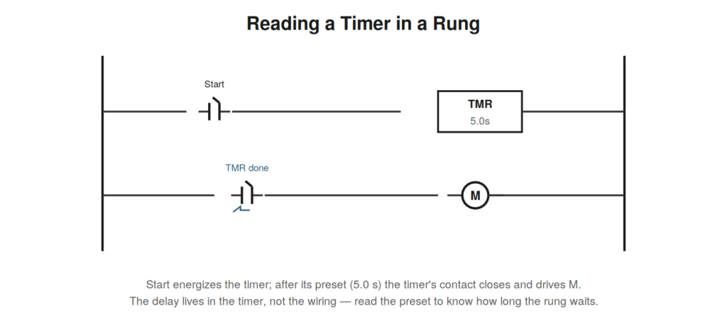
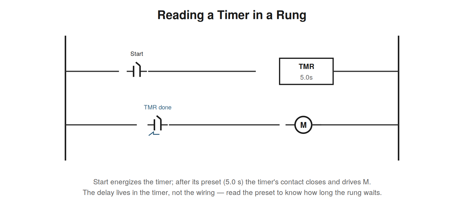
A timer introduces a delay into the logic, and it is read as a device that is energized by an input and, after a preset time, operates its own contacts. The most common type is the on-delay timer: when its input energizes, it begins timing, and after its preset delay its contacts operate, driving whatever depends on them. Reading a timer means finding two things: what energizes the timer, and what its contacts control, connected by the delay. A rung that energizes a timer, and another rung where the timer’s contact drives an output, together mean ‘when this input occurs, wait the preset time, then do that.’ The preset value tells you how long the delay is. Timers also come in off-delay and other varieties, but the reading approach is the same: identify what starts the timer, what its contacts do, and the delay between, which lives in the timer’s preset rather than anywhere in the wiring.
Counters
A counter tracks a number of events, operating its contacts when a preset count is reached. It is read as a device that counts pulses from an input — each operation of the counting input increments it — and operates its output contacts when the count reaches its preset. Reading a counter means identifying what it counts (the input that increments it), what resets it, and what its contacts control when the preset count is reached. A counter in a control circuit might count parts produced, cycles completed, or events detected, and its contact might trigger an action after a certain number. As with timers, the logic is read by finding the input that drives the counter, the reset, and the output its contacts control at the preset count, adding the dimension of quantity to the control logic.
Relay logic as a whole
Timers and counters join contacts and coils to form the complete vocabulary of relay and control logic, and reading a control drawing is reading how these elements combine. Contacts express conditions; coils are operated by conditions and operate further contacts; timers add delay; counters add counting. A complete control circuit chains these together: inputs and conditions drive coils, whose contacts become conditions for other coils, with timers and counters introducing time and quantity where needed, until the logic produces the outputs that run the machine. Reading it means following this chain — from the inputs and conditions, through the intermediate relays, timers, and counters, to the final outputs — understanding at each step what operates what. This is the full skill of reading control logic, and every element in this part of the book contributes a piece of the vocabulary that, combined, lets you read the logic of any relay-based control system, and by extension the PLC logic that has largely replaced it but reads by the same principles.
A worked example: reading a delayed-start circuit
A common use of a timer is a delayed start, and reading it demonstrates the timer-reading skill. The circuit: a start condition energizes an on-delay timer with a preset of, say, ten seconds; a separate rung has the timer’s normally-open contact (which closes when timing completes) driving a motor coil. Reading it: when the start condition occurs, the timer begins timing, and after ten seconds its contact closes and starts the motor — a ten-second delayed start. Perhaps the delay lets a warning horn sound first, or lets a lubrication pump run before the main motor. Reading the timer means finding what energizes it (the start condition), reading its preset (ten seconds), and finding what its contact controls (the motor coil), then assembling these into the behavior: ‘ten seconds after start, the motor runs.’ The delay is in the timer’s preset, not the wiring, so reading the preset is essential to knowing how long the circuit waits. This reading approach — energizing condition, preset, controlled output — applies to any timer in any circuit.
How PLC logic reads like relay logic
Although programmable controllers have largely replaced physical relays, the logic programmed into a PLC is typically drawn and read as ladder logic, so the skills of reading relay logic transfer almost directly. A PLC ladder program has rungs, contacts, and coils drawn just like a relay ladder, except the contacts and coils are program instructions referencing addresses rather than physical devices. A contact in PLC ladder references an input or internal bit; a coil references an output or internal bit; and the rung reads exactly as before — conditions on the left, output on the right, series as AND, parallel as OR. Reading PLC ladder logic is therefore the same skill as reading relay ladder logic, applied to a program instead of physical wiring. This continuity is a gift to the technician: learning to read relay ladder logic, as this book teaches, directly equips you to read the PLC ladder logic that runs most modern machines, because they share the same visual language and the same reading approach.
Case scenario: the delay that changed
A scenario involving a timer shows why reading the preset matters. A process that used to pause for a certain time between steps now pauses for a different time, disrupting the operation. Reading the timer circuit, the pause is created by a timer whose preset sets the delay, so a changed pause means a changed timer behavior — either the preset was altered, or the timer is malfunctioning. Reading the timer’s preset on the drawing tells you what the delay should be; comparing that to the actual behavior reveals whether the timer is running its correct preset or something has changed. If the drawing’s preset matches the original correct behavior but the actual pause differs, the timer may be faulty or its preset adjusted in the field; if the drawing’s preset itself was changed, the drawing reveals the intended new behavior. Reading the timer — finding it, reading its preset, comparing to actual behavior — localizes a timing problem to the timer and clarifies whether the issue is a faulty timer, an adjusted preset, or a drawing that no longer matches. Timing faults are opaque without reading the timer; with it, they become specific.
On-delay versus off-delay timers
Reading timers accurately requires distinguishing the common timer types, especially on-delay from off-delay, because they behave oppositely and confusing them misreads the timing. An on-delay timer begins timing when its input energizes and operates its contacts after the preset delay — so its timed contact operates a set time after the input turns on. An off-delay timer operates its contacts immediately when energized but delays their return after the input turns off — so its timed contact stays operated for a set time after the input turns off. Reading a timer means noting which type it is (indicated by the symbol or a label) and understanding its behavior accordingly: on-delay delays the turn-on, off-delay delays the turn-off. Getting this wrong inverts your understanding of when the timer’s contact operates relative to its input. The drawing indicates the timer type, and reading it carefully — on-delay or off-delay — is essential to correctly reading when the timed action occurs, just as reading a contact’s resting state is essential to reading its logic. The timer type is to timing what resting state is to contacts: a small indication that determines the behavior.
Reading cascaded timers and complex timing
Complex timing behavior is often built from multiple timers working together — cascaded or combined — and reading such arrangements requires following how the timers interact. One timer’s completion might start another, creating a sequence of delays; timers might run in parallel for different functions; a timer might be reset by another’s action. Reading cascaded timers means following the chain: this timer times out and starts that one, which times out and does something else, building a complex timing sequence from individual timers. This is how relay and PLC logic creates sophisticated timing — not from one complex timer but from simple timers combined. Reading it requires the same approach as a single timer (what starts each, its preset, what its contacts do) applied to each timer, plus following how they connect. A sequence of timed events, a repeating cycle, a complex delay pattern — these are built from timers interacting, and reading them means tracing the interactions. The skill scales from the single timer to arrangements of many: read each timer’s role, then follow how they combine, and even complex timing becomes readable as a structured combination of individual timers each doing its simple job of delaying by its preset.
Case: the counter that stopped the line
A counter reaching its preset and taking an action can stop a line in ways that puzzle until the counter is read. A production line halted for no obvious reason, with no fault indicated. Reading the logic revealed a counter that counted cycles and, at a preset count, stopped the line — perhaps for a scheduled maintenance interval or a batch limit. The line had reached the preset count, and the counter had correctly stopped it, which looked like an unexplained halt until the counter was read. Reading the counter — what it counted, its preset, what its contacts did at the preset — explained the halt: the count reached the preset, and the counter acted as designed to stop the line. The resolution was to reset the counter (and address whatever the count signified, such as performing the due maintenance), after which the line ran again. This case shows reading counters to explain count-based behavior: a machine action triggered by a counter reaching its preset can appear as an unexplained event until the counter is read, revealing that the preset count was reached and the counter acted as designed. Reading the counter — its count, preset, and action — turns an unexplained halt into an understood, designed response to reaching a count, which is resolved by resetting and addressing what the count represents, not by hunting for a nonexistent fault.
Completing the logic vocabulary
With timers and counters, the vocabulary of relay and control logic is complete, and the reader who has mastered contacts, coils, timers, and counters can read the logic of virtually any relay-based or PLC control system, because these elements combine to express all of it. Everything in control logic is built from these elements: contacts expressing conditions, coils operated by and operating contacts, timers adding delay, counters adding counting. However complex a control system, it is these elements combined, and the reader fluent in all of them can read any such system by following how the elements combine. This completeness is worth appreciating: the vocabulary is finite and now fully covered, so there is no further fundamental element to learn — only more complex combinations of the same elements, which the reading skills handle. The reader who has worked through the logic vocabulary has the complete toolkit for reading control logic, and further growth is in fluency and handling complexity, not in new fundamentals. This is encouraging: the fundamentals of reading control logic are finite and now complete, and mastery of them equips you to read any control logic, however sophisticated, as a combination of the elements you know. The vocabulary is complete; what remains is practice in reading its ever more elaborate combinations, all built from the contacts, coils, timers, and counters now mastered.