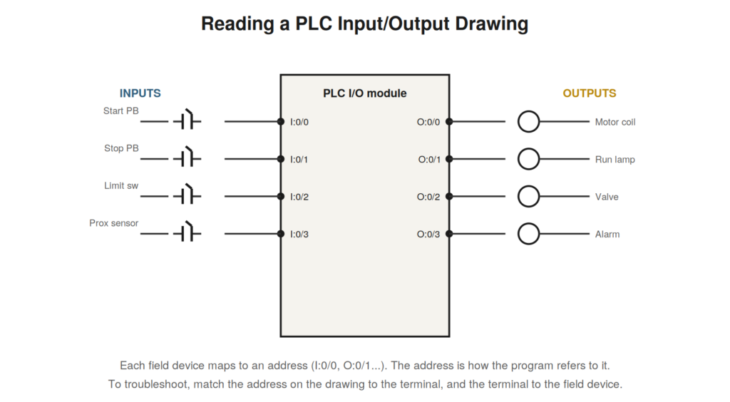
Modern industrial control is dominated by programmable logic controllers (PLCs), and while the control logic now lives in software, the drawings that show how a PLC connects to the physical world — its input and output wiring — are essential to reading and troubleshooting these systems. PLC I/O drawings read by the same principles as the rest, with the addition of addresses that link the wiring to the program.
Inputs, outputs, and addresses
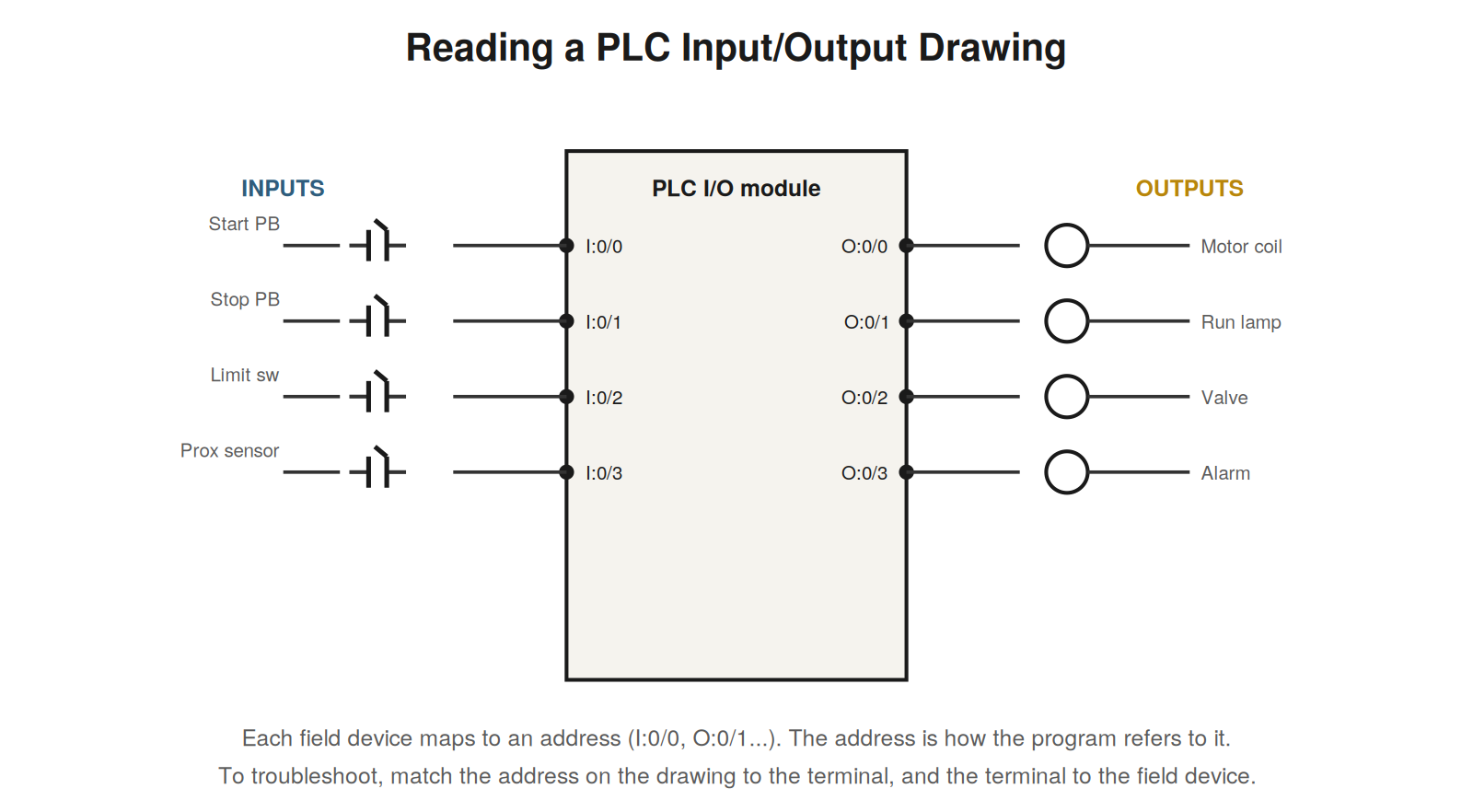
A PLC I/O drawing shows the connections between field devices and the PLC’s input and output modules. Input devices — buttons, switches, sensors — wire to input points on the PLC, each point having an address that the program uses to read that input’s state. Output devices — contactor coils, lamps, valves — wire to output points, each with an address the program uses to control it. The address is the crucial addition: it is how the software refers to a physical point, so I:0/0 might be the address of the input where the Start button connects, and O:0/1 the output where the run lamp connects. Reading a PLC I/O drawing means matching each field device to its I/O point and its address, understanding that the address is the name by which the program knows that physical connection.
From field device to program
The power of the address is that it links the physical wiring to the program logic, and reading it lets you cross between them. When troubleshooting, you can go from a field device, to the terminal and I/O point it connects to on the drawing, to the address of that point, and then into the program to see how that address is used in the logic. Conversely, from a program address you can find, via the drawing, which physical point and field device it corresponds to. This linking is essential for troubleshooting PLC-controlled systems, because the fault might be in the field device, the wiring, the I/O point, or the program, and the address is the thread that connects the physical drawing to the software logic. Reading a PLC I/O drawing well means using addresses to move fluidly between the physical connections it shows and the program logic it enables.
Troubleshooting with I/O drawings and indicators
PLC systems offer a powerful troubleshooting aid that reading the I/O drawing unlocks: the status indicators on the I/O modules. Each input and output point typically has an indicator LED showing its state, and reading the drawing tells you which point corresponds to which device and address. This lets you verify the physical side directly: if a Start button is pressed but its input indicator does not light, the fault is on the input side — the button, the field wiring, the terminal, the input point — before the program is even involved. If an output’s indicator lights but the device does not act, the program has commanded the output and the fault is on the output side — the wiring, the device. Reading the I/O drawing to connect each indicator to its device and address turns the module’s indicators into a diagnostic that splits faults between the field wiring and the program, one of the most efficient techniques for PLC-controlled systems and a direct payoff of reading the I/O drawing.
A worked example: the input that never comes on
A classic PLC fault reads cleanly from the I/O drawing: an input that should turn on but does not. An operator presses a button, but the machine does not respond. Reading the I/O drawing, the button connects to a specific input point with a specific address, and that point has a status indicator on the module. The diagnostic: press the button and watch the input indicator. If the indicator does not light when the button is pressed, the PLC is not seeing the input, so the fault is on the input side — the button, the field wiring, the terminal, the input point — all before the program. If the indicator does light but the machine still does not respond, the input is reaching the PLC and the fault is in the program logic or downstream. Reading the I/O drawing to connect the button to its input point, address, and indicator is what makes this diagnosis possible: the indicator becomes a window into whether the physical signal reaches the controller, splitting the fault between field and program with a single observation.
Reading exercise: building the address map
A valuable exercise for PLC I/O drawings is to build an address map — a list pairing each I/O address with the field device it connects to and the terminal it uses. Read the I/O drawing and for each input and output, note its address, its device, and its terminal: I:0/0 is the Start button at terminal 5; O:0/1 is the run lamp at terminal 12; and so on. This map, built by reading the drawing, is exactly what you need for troubleshooting, because it lets you move instantly between an address (in the program), a device (in the field), and a terminal (for measuring). Many technicians build such a map for machines they maintain, and the act of building it from the drawing deepens their reading of the I/O connections. The exercise also reveals the structure of the machine’s I/O — how many inputs and outputs, what they connect to — giving a clear picture of the machine’s interface to the physical world. Building the address map is reading the I/O drawing thoroughly, and it produces a reference that makes all subsequent troubleshooting of that machine faster.
Sinking, sourcing, and wiring details
PLC I/O drawings include wiring details — how devices are powered and how signals return — that reading correctly matters for understanding and troubleshooting the I/O. Digital inputs and outputs are wired in particular configurations (often described as sinking or sourcing) that determine the direction of current flow and how devices connect to the module and its common or power connections. Reading the I/O drawing includes reading these details: which terminal is the signal, which is common or power, how the field device connects between them. This matters in troubleshooting because a wiring detail — a common not connected, a power supply for the I/O missing — can disable an input or output in ways that reading the drawing reveals. While the full theory of I/O wiring configurations is beyond a reading guide, the point for the reader is to read the I/O drawing’s wiring details, not just the device-to-address mapping, because those details are part of how the I/O works and where it can fail. Reading them completes your understanding of the I/O connection, from the field device through the wiring configuration to the module point, so that a fault in the wiring detail is within your reading rather than a mystery outside it.
Reading I/O drawings alongside the program
The full power of reading PLC I/O drawings comes from using them alongside the program, moving between the physical I/O drawing and the ladder logic program to understand the complete system. The I/O drawing shows the physical connections and addresses; the program shows how those addresses are used in the logic. Reading them together, you can follow a field device to its address (via the I/O drawing) and then see how that address is used in the program (via the ladder logic), understanding the complete path from physical device to logical use. This integrated reading is essential for troubleshooting PLC systems, where a problem might be physical (found via the I/O drawing) or logical (found in the program), and the address connects the two. Reading the I/O drawing alone tells you the connections; reading it with the program tells you how the connections are used to control the machine. The modern equivalent of reading a full relay control scheme is reading the PLC I/O drawing together with the program, using addresses to move between the physical and logical views, and this combined reading is how you fully understand and troubleshoot a PLC-controlled machine, with the I/O drawing as the bridge from the physical world to the program that controls it.
Case: the output commanded but not acting
A PLC output that the program commands but that does not act is diagnosed cleanly by reading the I/O drawing and using the indicator. A machine function was not occurring, and reading the I/O drawing, the function’s output had a specific address and a status indicator. The technician observed the output indicator: it was lit, meaning the program was commanding the output — the logic had decided to activate it. Yet the function did not occur. The lit indicator located the fault after the output point: the program commanded correctly (indicator lit), but the physical output — the wiring, the device — was not responding. Reading the I/O drawing to connect the indicator, address, and device, the technician checked the output wiring and device, finding the fault there (a disconnected output device or open wiring). This case shows the I/O indicator as a diagnostic split: a lit output indicator means the program commanded the output, so a function not occurring despite the lit indicator is a fault after the output point, in the physical output. Reading the I/O drawing to interpret the indicator — commanded (lit) but not acting — directs the search to the output wiring and device, past the program which has done its job. The indicator, read via the drawing, splits the fault between program and physical output, and here located it in the physical output, found by checking the wiring and device the drawing shows connected to that output point.
Reading modern systems with confidence
Modern PLC-controlled systems can seem intimidating to those trained on relay logic, but reading their I/O drawings with the skills this book builds gives the confidence that they are readable by the same principles, extended with addresses. The PLC I/O drawing reads like any other drawing — devices, connections, symbols — with the addition of addresses linking the physical to the program, and the program itself reads as ladder logic by the same rules as relay ladder logic. So the relay-trained reader is not lost before a PLC system but well-equipped: the reading skills transfer, the I/O drawing is readable, and the program logic is familiar ladder logic. This confidence matters because PLC systems dominate modern industry, and a reader who felt they could not handle them would be limited to older equipment. In fact, the reading skills apply directly, and understanding the additions — addresses, I/O drawings, program-physical linkage — completes the ability to read modern systems. The reader who approaches a PLC system knowing their reading skills apply, that the I/O drawing is readable and the program is ladder logic, reads it with confidence rather than intimidation. Modern systems are readable by the skills this book builds, extended with the address concept, and approaching them with that confidence — rather than as something alien — is warranted, because they are built on the same readable foundations as the relay logic that preceded them.