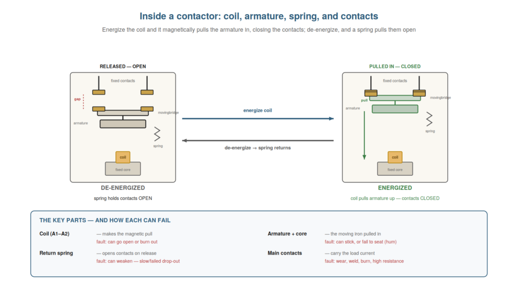
To troubleshoot a contactor well, it helps to understand what is inside it — the coil, the magnetic core and armature, the return spring, and the contacts — because each part can fail in its own way, and knowing the mechanism lets you reason about the symptoms. A contactor is an electromagnet operating a set of contacts, and understanding how the electromagnet pulls the contacts closed, and the spring pulls them open, is the key to diagnosing faults like failure to pull in, failure to drop out, and humming. This chapter opens up the contactor.
The electromagnet: coil, core, and armature
The heart of a contactor is its electromagnet — the coil, the fixed core, and the moving armature — and understanding how they work together explains how the contactor operates and how it can fail to. When current flows through the coil, it magnetizes the fixed iron core, which attracts the moving armature, pulling it toward the core. The armature carries the moving contacts, so as it is pulled in, the contacts close. The strength of this magnetic pull depends on the coil current (hence the coil voltage): enough voltage, and the armature is pulled firmly home; too little, and it may not seat properly. So the electromagnet converts coil current into the mechanical pull that closes the contacts. Understanding this explains key faults: an open or burnt coil produces no pull (the contactor will not pull in), and insufficient coil voltage produces a weak or incomplete pull (the contactor hums or chatters, unable to seat firmly). So understanding the electromagnet — coil magnetizing core, core pulling armature, armature closing contacts — explains how the contactor operates and the faults of failing or weak pull. Understanding the electromagnet of a contactor — the coil magnetizing the fixed core, which pulls the moving armature that carries the contacts closed, with the strength of the pull depending on the coil voltage — explains both how the contactor operates and how it can fail to, so that you understand a no-pull-in fault as no magnetic pull (an open or unfed coil) and a hum or chatter as a weak or incomplete pull (insufficient coil voltage or an armature that cannot seat), which connects the internal mechanism directly to the symptoms you will diagnose and grounds your troubleshooting in how the contactor actually works.
The return spring and drop-out
The counterpart to the magnetic pull is the return spring, and understanding its role explains how the contactor drops out and the faults where it fails to. When the coil is energized, the magnetic pull overcomes the spring and holds the armature in (contacts closed). When the coil is de-energized, the magnetic pull vanishes, and the return spring pushes the armature back to its resting position, opening the contacts — this is drop-out. So the spring is what opens the contacts when the coil is de-energized; the device relies on it to release. Understanding this explains drop-out faults: if the spring is weak or broken, the contactor may drop out slowly, erratically, or not at all; and if the mechanism is jammed or the contacts are welded, the spring cannot open them even though it is trying. A contactor that stays in when de-energized is a spring-versus-stuck-mechanism question. So understanding the return spring and drop-out — the spring opening the contacts when the coil releases — explains how the contactor releases and the faults of failing to drop out. Understanding the return spring and drop-out — the spring that pushes the armature back to open the contacts when the coil is de-energized, opposed while energized by the magnetic pull — explains how the contactor releases and the faults where it fails to, so that you understand a slow or erratic drop-out as a weak spring, and a failure to drop out at all as either a still-energized coil (the pull persists), a jammed mechanism, or welded contacts the spring cannot open, which connects the spring’s role to the important and potentially hazardous class of faults where a contactor stays in when it should release.
The contacts: main and auxiliary
The working output of a contactor is its contacts, and understanding the distinction between main and auxiliary contacts is important because they do different jobs and fail differently. The main contacts are the heavy contacts that switch the power circuit — built to make and break large currents, they carry the motor or load current and take the punishment of switching it. The auxiliary (aux) contacts are smaller, lower-rated contacts that operate with the main ones but are used by the control circuit — for seal-in, interlocking, and feedback (signalling the contactor’s state). So a contactor has heavy main contacts for the power and light aux contacts for control. Understanding this distinction matters for troubleshooting: the main contacts, switching heavy loads, are prone to wear, burning, and welding; the aux contacts, carrying small control currents, fail more subtly (not making, causing a seal-in to drop out). And you must not confuse them — an aux contact is rated far below the main contacts and cannot switch power. So understanding main versus auxiliary contacts — heavy power contacts versus light control contacts — clarifies their different jobs and failure modes. Understanding the main and auxiliary contacts of a contactor — the heavy main contacts that switch the power circuit and take the punishment of large currents, and the smaller auxiliary contacts used by the control circuit for seal-in, interlocking, and feedback — clarifies their different jobs and failure modes, so that you recognize the main contacts as prone to wear, burning, and welding from switching heavy loads while the aux contacts fail more subtly (not making, dropping out a seal-in), and you never confuse the low-rated aux contacts with the power-switching main contacts, which is essential for correctly diagnosing and working with the two kinds of contacts a contactor provides.
Arc chutes and how contacts break current
A detail worth understanding is the arc chute and how a contactor breaks current, because it explains a key part of the contactor’s construction and why contacts wear. When a contactor’s main contacts open under load, they draw an arc — a conducting plasma that continues the current momentarily as the contacts separate. This arc must be extinguished quickly, or it damages the contacts and could sustain the current. Contactors have arc chutes (also called arc extinction chambers): structures over the contacts that stretch, cool, and split the arc to extinguish it rapidly, protecting the contacts and safely breaking the current. Understanding this explains why a contactor is built the way it is (the arc chutes over the contacts), why the main contacts are made of special arc-resistant materials, and why switching heavy loads wears the contacts (each break draws an arc that erodes them despite the chute). So understanding arc chutes and arc-breaking explains the contactor’s construction and contact wear. Understanding arc chutes and how contacts break current — the arc drawn as contacts open under load, and the arc chute that stretches, cools, and extinguishes it to protect the contacts and break the current safely — explains a key part of the contactor’s construction and why contacts wear, so that you understand why contactors have arc chutes over the main contacts and use arc-resistant materials, and why switching heavy loads erodes the contacts despite these measures (each break drawing an arc), which grounds your understanding of contact wear and the contactor’s design in the physics of breaking current under load.
Scenario: the contactor that buzzed
A scenario shows how understanding the contactor’s mechanism explains a fault. A contactor buzzed loudly and would not seat properly, and the technician, understanding the electromagnet and armature, reasoned about the cause. The buzz meant the armature was not seating fully against the core — an air gap remained, so the AC pull pulsated and the contactor buzzed. Understanding the parts, he considered what could prevent seating: dirt or debris on the pole faces (the mating surfaces), a broken shading ring, or mechanical binding. He inspected the pole faces and found them dirty with accumulated grime, holding the armature off its seat. Cleaning the pole faces let the armature seat fully, and the buzz stopped. Understanding the mechanism — that seating requires clean pole faces and that a gap causes the buzz — led him straight to the cause. This scenario shows how understanding the contactor’s mechanism explains and locates a buzzing fault. Understanding the electromagnet, armature, and the need to seat fully led the technician to inspect and clean the pole faces. It reinforces that knowing the mechanism explains faults like buzzing (an unseated armature) and directs the fix. The scenario reinforces understanding the contactor’s insides: knowing the electromagnet pulls the armature to seat against the core, and that a gap causes an AC buzz, led the technician to inspect and clean the dirty pole faces preventing seating, illustrating how understanding the mechanism directs you to the mechanical cause of a fault like buzzing rather than leaving it a mystery.
Contact bounce and multi-pole timing
A nuance worth understanding is contact bounce and the timing of a contactor’s poles closing, because it explains some subtle switching behaviors. When a contactor’s contacts close, they can bounce briefly (making and breaking rapidly for a few milliseconds as the mechanism settles) before settling closed — usually harmless, but a source of extra arcing and, occasionally, of noise on the switched circuit. And a contactor’s three poles may not close at exactly the same instant — slight mechanical differences mean one pole may make marginally before another. Usually this is inconsequential, but understanding it explains rare issues: a pole that makes significantly late or early (from wear or damage) could cause momentary imbalance, and severe bounce could stress the contacts. Understanding contact bounce and pole timing explains these subtle behaviors and reminds you that a contactor’s closing is not perfectly instantaneous or simultaneous. So understanding contact bounce and multi-pole timing explains subtle switching behaviors of a contactor. Understanding contact bounce and multi-pole timing — the brief bounce as contacts settle closed, and the slight differences in when a contactor’s poles make — explains some subtle switching behaviors, so that you understand a contactor’s closing involves a brief settling bounce (a source of extra arcing) and that its poles may not make at exactly the same instant, which explains rare issues like a significantly late-making pole causing momentary imbalance and rounds out your understanding of the contactor’s real, not idealized, switching behavior.
The mechanism as a map of faults
To close, it helps to see the contactor’s mechanism as a map of its faults, because knowing the parts tells you what can fail and how. Each part of the contactor corresponds to a class of fault: the coil (open, burnt, wrong voltage — no or weak pull), the armature and core (sticking, not seating — no pull-in or hum), the return spring (weak, broken — slow or failed drop-out), and the contacts (wear, welding, burning — high resistance, stuck on, not making). So understanding the mechanism is understanding the fault map: the parts are the fault locations, and how each fails is the fault types. This framing makes the contactor’s faults comprehensible rather than a list to memorize — you reason from the part to its failure. So seeing the mechanism as a map of faults makes the contactor’s faults comprehensible from its parts. Understanding the contactor’s mechanism as a map of its faults — each part (coil, armature and core, return spring, contacts) corresponding to a class of fault — makes the faults comprehensible from the parts, so that you reason from the mechanism to its failures (the coil to no or weak pull, the armature to sticking or hum, the spring to drop-out faults, the contacts to wear, welding, and burning) rather than memorizing a list, which turns understanding the contactor’s insides into a map of where and how it fails, the deeper value of knowing the mechanism.