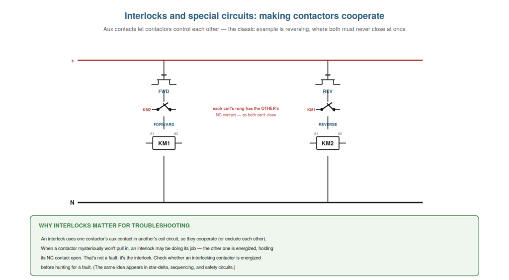
Contactors and relays are often wired to cooperate through interlocks and special circuits, and understanding these — especially interlocking, where one contactor’s contact controls another — is important, because an interlock can make a contactor appear faulty when it is simply doing its job. The classic example is a reversing circuit, where two contactors must never close at once, each held off by the other. Understanding interlocks lets you recognize when a contactor is being held off by design rather than by a fault. This chapter covers interlocks and special circuits.
How interlocking works
Understanding how interlocking works — one contactor’s contact in another’s coil circuit — explains a circuit arrangement that appears throughout control and can masquerade as a fault. In an interlock, one contactor’s aux contact is placed in another contactor’s coil circuit, so that the first contactor’s state controls whether the second can energize. The classic case is reversing: the forward contactor’s coil circuit contains the reverse contactor’s normally-closed aux contact, and vice versa. So if the reverse contactor is energized, its NC aux contact (in the forward coil circuit) is open, preventing the forward contactor from energizing — and the reverse the other way. This ensures both can never be energized at once (which, in reversing, would short the supply). So interlocking uses cross-wired aux contacts to make contactors exclude (or require) each other. Understanding this explains the arrangement and, crucially for troubleshooting, that a contactor held off by an interlock is not faulty — it is prevented by design because the interlocking contactor is energized. So understanding how interlocking works — cross-wired aux contacts making contactors control each other — explains a common arrangement and how it can masquerade as a fault. Understanding how interlocking works — one contactor’s aux contact placed in another’s coil circuit so their states control each other, as in a reversing circuit where each holds the other off through a normally-closed aux contact — explains an arrangement that appears throughout control and can masquerade as a fault, so that you understand contactors can be wired to exclude or require each other, and crucially that a contactor held off by an interlock is not faulty but prevented by design because the interlocking contactor is energized, which is essential for correctly diagnosing a contactor that ‘won’t pull in’ when an interlock is simply doing its job.
When an interlock looks like a fault
The important troubleshooting lesson is that an interlock can look exactly like a fault, and understanding this saves you from hunting a phantom fault when a contactor is correctly held off. The symptom: a contactor will not pull in even though you are commanding it and it seems to have its coil circuit. Understanding interlocks provides a key explanation to check: is an interlocking contactor energized, holding this one off through its NC aux contact? If so, this contactor cannot pull in — not because it is faulty, but because the interlock is working: the other contactor is on, so this one is (correctly) prevented. So before hunting for a fault in a contactor that will not pull in, you check whether an interlock is holding it off — is the interlocking contactor energized? This is not a fault to fix but a condition to understand (why is the other contactor on when it should not be, if that is the real issue). Understanding that an interlock looks like a fault directs you to check the interlocking contactor’s state before diagnosing the held-off one as faulty. So understanding when an interlock looks like a fault — a contactor held off by an energized interlocking contactor — saves you from hunting a phantom fault. Understanding when an interlock looks like a fault — a contactor that will not pull in because an interlocking contactor is energized and holding it off through a normally-closed aux contact, not because it is faulty — saves you from hunting a phantom fault, so that when a contactor will not pull in you first check whether an interlock is holding it off (is the interlocking contactor energized?) before diagnosing the held-off contactor as faulty, which correctly recognizes the interlock doing its job and redirects your attention to why the interlocking contactor is energized if that is the real question, rather than wrongly troubleshooting a contactor that is being correctly prevented.
Other special circuits
Beyond simple interlocking, several special circuits use contactors and relays in particular ways, and understanding that they exist — and share the same principles — helps you approach them without being thrown. Star-delta starting uses contactors to connect a motor first in star (for reduced starting current) then in delta (for running), sequenced by a timer and interlocked so the wrong combinations cannot occur. Sequencing circuits use contactors and relays to start things in order. Safety circuits use redundant, monitored contacts to ensure safe operation. Timing relays introduce deliberate delays. These circuits can look complex, but understanding that they are built from the same coil-and-contacts principles — coils energized by conditions, contacts (including aux and interlock contacts) implementing the logic — lets you approach them the same way: find the coils and their conditions, find the contacts and what they do, and trace the logic. So the same troubleshooting method applies, just to a more elaborate circuit. Understanding that special circuits share the same principles helps you approach them methodically rather than being intimidated. So understanding other special circuits — star-delta, sequencing, safety, timing — as built from the same principles helps you troubleshoot them with the same method. Understanding other special circuits — star-delta starting, sequencing, safety circuits, and timing relays, all built from the same coil-and-contacts principles with coils energized by conditions and contacts implementing the logic — helps you approach them methodically rather than being thrown by their apparent complexity, so that you troubleshoot even an elaborate circuit the same way (finding the coils and their conditions, the contacts and their jobs, and tracing the logic), recognizing that special circuits are combinations of the same basic elements and yield to the same systematic approach as any control circuit.
Electrical and mechanical interlocks
A detail worth understanding is that interlocks can be electrical, mechanical, or both, because reversing contactors often use both and this affects troubleshooting. An electrical interlock uses one contactor’s NC aux contact in the other’s coil circuit (as described), preventing both coils being energized at once electrically. A mechanical interlock is a physical linkage between two contactors (often reversing pairs) that physically prevents both from closing at once — a lever or bar that blocks one from pulling in while the other is in. Reversing contactors frequently use both: the electrical interlock in the coil circuits and a mechanical interlock physically preventing simultaneous closure, for safety redundancy. Understanding this matters for troubleshooting: a contactor held off might be blocked electrically (the other’s aux contact) or mechanically (the physical interlock jammed or engaged), and a mechanical interlock can itself fail (jamming a contactor). So understanding electrical and mechanical interlocks explains the redundant interlocking of reversing pairs and an extra fault possibility. Understanding electrical and mechanical interlocks — the electrical interlock using an NC aux contact in the other’s coil circuit and the mechanical interlock physically linking two contactors to prevent simultaneous closure, often both used on reversing pairs — explains the redundant interlocking of reversing contactors and an extra fault possibility, so that you understand a contactor may be held off electrically or blocked mechanically, and that a mechanical interlock can itself jam a contactor, which adds the mechanical interlock to your understanding of how contactors are prevented from dangerous combinations and to the possible causes of a contactor that will not close.
Scenario: the contactor held off by design
A scenario shows interlock understanding preventing a phantom-fault chase. A reversing contactor (the forward one) would not pull in when commanded, and the technician was about to hunt for a fault in it — until he considered the interlock. Understanding that reversing contactors interlock (each held off by the other), he checked the reverse contactor: it was energized. So the forward contactor could not pull in because the reverse contactor’s NC aux contact (in the forward coil circuit) was open — the interlock doing its job, correctly preventing both from closing at once. The forward contactor was not faulty at all. The real question was why the reverse contactor was energized when forward was commanded — which turned out to be a control-logic issue (a stuck reverse command). Understanding the interlock saved him from hunting a phantom fault in a healthy forward contactor and redirected him to the real cause. This scenario shows interlock understanding preventing a phantom-fault chase. Understanding that reversing contactors interlock led the technician to check the reverse contactor before blaming the forward one. It reinforces that a contactor held off by an interlock is not faulty — check the interlocking contactor first. The scenario reinforces interlocks: understanding that reversing contactors hold each other off led the technician to find the reverse contactor energized (holding the forward one off by design) rather than hunting a phantom fault in a healthy forward contactor, illustrating how understanding interlocks redirects you from the held-off contactor to the interlocking one and the real control-logic cause behind it.
Star-delta: a worked interlock example
A worked example worth understanding is the star-delta starter, because it shows several contactors, a timer, and interlocks working together — and how to approach such a circuit. A star-delta starter uses three contactors: a main (line) contactor, a star contactor, and a delta contactor, plus a timer. On starting, the main and star contactors close, connecting the motor in star (reduced voltage/current for a gentler start). After a timed delay, the star contactor opens and the delta contactor closes, switching the motor to delta (full running connection). The star and delta contactors are interlocked (each holding the other off) so both can never close at once (which would short the supply). Understanding this shows how to approach the circuit: identify the three contactors and their roles, the timer that sequences the transition, and the interlocks. Troubleshooting follows the method — which contactor is (not) doing its job, is the timer sequencing, are the interlocks holding correctly? So the star-delta starter, understood as contactors + timer + interlocks, yields to the systematic approach. Understanding star-delta as a worked interlock example shows how to approach a multi-contactor sequenced circuit. Understanding the star-delta starter as a worked interlock example — the main, star, and delta contactors with a timer sequencing star (reduced-current start) to delta (full running), the star and delta interlocked so both never close at once — shows how to approach a multi-contactor sequenced circuit, so that you identify the contactors and their roles, the timer sequencing the transition, and the interlocks, and troubleshoot by the method (which contactor is not doing its job, is the timer sequencing, are the interlocks holding?), which demonstrates that even an elaborate special circuit is contactors, a timer, and interlocks yielding to the systematic approach.
Recognizing a device held off by design
To close, it is worth emphasizing the key lesson of this chapter: recognizing when a device is held off by design rather than by a fault, because this recognition saves much wasted effort. Interlocks, safety contacts, and sequencing conditions all deliberately prevent a contactor from energizing under certain conditions — and when they do, the contactor not pulling in looks exactly like a fault but is the circuit working correctly. The lesson is to recognize this possibility: before diagnosing a contactor that won’t pull in as faulty, ask whether it is being held off by design (an interlock active, a safety contact open, a sequencing condition not met). Recognizing a held-off device redirects you from a phantom fault to the real question (why is the holding condition present?) or confirms correct operation. So recognizing a device held off by design is the key lesson that prevents chasing phantom faults. Understanding this saves the effort of troubleshooting a correctly-functioning circuit. So recognizing a device held off by design prevents chasing phantom faults. Understanding the key lesson of recognizing when a device is held off by design — an interlock, safety contact, or sequencing condition deliberately preventing a contactor from energizing, which looks like a fault but is correct operation — saves much wasted effort, so that before diagnosing a won’t-pull-in contactor as faulty you ask whether it is being held off by design, which redirects you from a phantom fault to the real question or confirms correct operation, the recognition that prevents the common waste of troubleshooting a circuit that is actually working as intended.