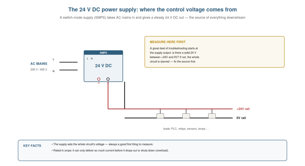
Every 24 volt DC control circuit begins at its power supply — the source of the voltage that everything downstream depends on — and understanding the supply is both a natural starting point and, very often, the first place to measure when troubleshooting. If the supply is not delivering a solid 24 volts, nothing else in the circuit can work properly, so a great deal of troubleshooting starts here. This chapter explains the power supply in the practical terms a maintenance technician needs.
What the supply does
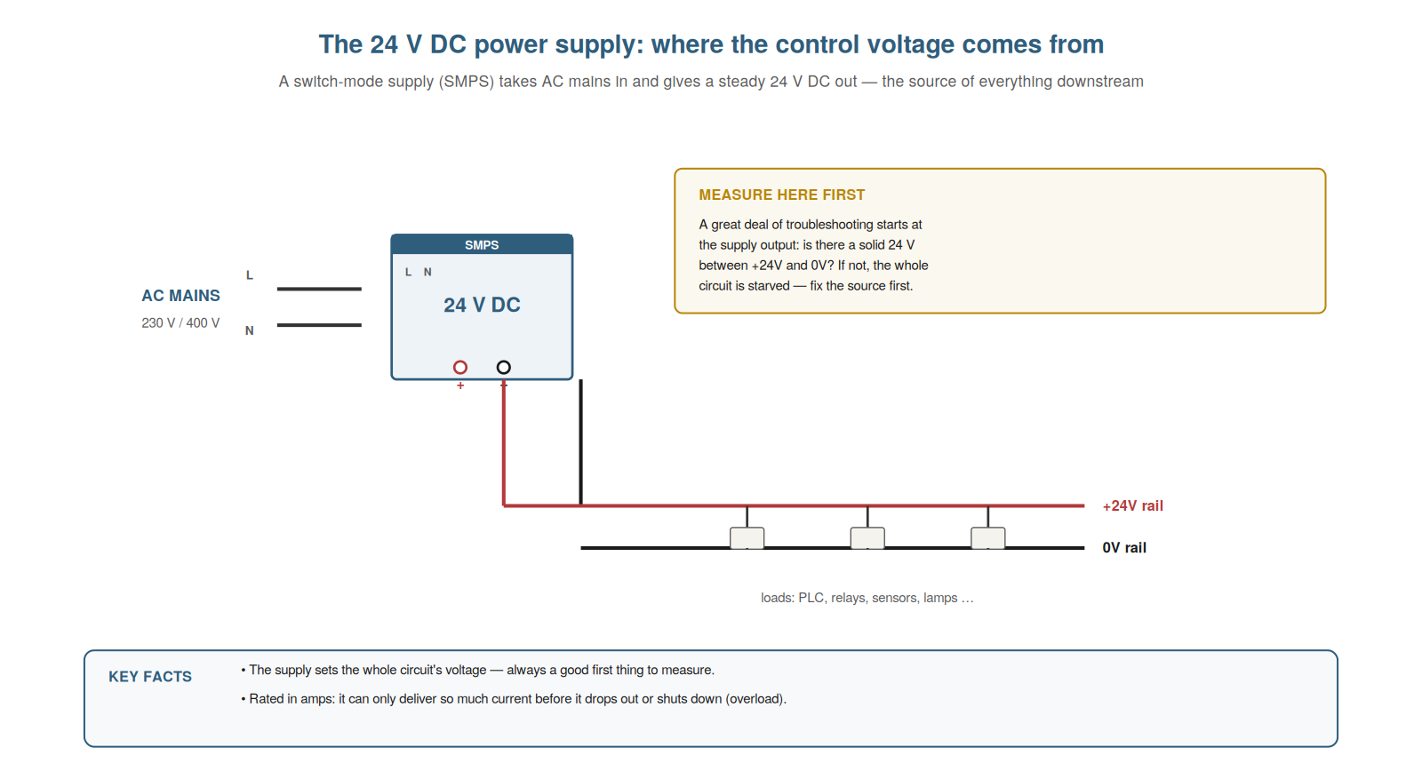
Understanding what the power supply does — converting AC mains into a steady 24 volts DC — clarifies its central role as the source of the whole control circuit. The supply, typically a switch-mode power supply (SMPS) on the DIN rail, takes in AC mains voltage (230 or 400 volts) and converts it into a steady, regulated 24 volts DC, which it provides at its output terminals: a positive (+24V) and a zero-volt (0V) terminal. From these, the +24V and 0V rails run out to feed everything in the control circuit. So the supply is the source: it creates the 24 volts DC that the whole control circuit uses, converting the dangerous mains into the safe, standard control voltage. Understanding this role — the supply as the converter and source of the control voltage — clarifies why it is so central: everything downstream depends on the supply doing its job. If the supply fails or falters, the whole circuit is affected. Understanding what the power supply does — converting AC mains into the steady 24 volts DC that feeds the entire control circuit — clarifies its central role as the source everything downstream depends on, so that you recognize the supply as the origin of the control voltage and understand why its health is fundamental: a supply not delivering a solid 24 volts starves the whole circuit, which is why the supply is both the natural starting point for understanding the circuit and very often the first place to measure when something across the whole panel is not working.
Measuring the supply first
A practical habit that flows directly from understanding the supply is measuring it first when a broad fault occurs, and understanding why makes this an efficient starting point. Because the supply feeds everything, a problem at the supply affects everything: if the whole panel is dead, or many devices are misbehaving, the supply is a prime early suspect. Measuring it is quick and decisive: put the meter across the supply’s output (+24V to 0V) and read the voltage. A solid 24 volts confirms the source is good, so you look downstream. A low, missing, or unstable reading points to the supply or its input — a failed supply, a blown input fuse, a lost mains feed, or an overload shutting it down. So measuring the supply first, when a broad fault occurs, quickly confirms or eliminates the source, focusing the rest of your diagnosis. Understanding why to measure the supply first — because it feeds everything, so a supply fault is broad and a quick measurement is decisive — makes it an efficient starting point for wide faults. It reinforces that measuring the supply output (+24V to 0V) early confirms or eliminates the source when many things are affected. Understanding to measure the supply first when a broad fault occurs — because the supply feeds everything, so a supply problem affects everything and a quick measurement of its output decisively confirms or eliminates it — makes measuring the supply an efficient starting point for wide-ranging faults, so that when the whole panel is dead or many devices misbehave, you begin by reading the 24 volts at the supply output, which either confirms a good source (directing you downstream) or reveals a supply, input, or overload problem (directing you to the source), quickly focusing a diagnosis that would otherwise be unfocused.
When the supply is overloaded
A particular supply-related fault worth understanding is the overload, because it explains a puzzling situation where the supply seems to fail intermittently or under certain conditions. A power supply can only deliver so much current — its rated amperage — and if the load draws more than this (too many devices, or a fault drawing excess current like a partial short), the supply may respond by dropping its voltage, shutting down, or cycling on and off, protecting itself from the overload. This can look puzzling: the supply seems to fail, but only under certain conditions (when a particular device switches on, adding load, or when a fault draws current). Understanding overload explains this: the supply is being asked for more current than it can give, so it falters. The cause is often a fault downstream drawing excess current (a developing short) rather than the supply itself being bad. So understanding supply overload — the supply faltering under excess current draw — explains conditional or intermittent supply failures and points to a downstream current-drawing fault. Understanding when the supply is overloaded — that a supply asked for more current than its rating may drop, shut down, or cycle, often because a downstream fault is drawing excess current — explains a puzzling class of supply failures that appear only under certain conditions or intermittently, so that when a supply seems to fail when a particular device switches on or a fault develops, you recognize a possible overload and look downstream for the excess current draw (a developing short or a device drawing too much) rather than assuming the supply itself is simply bad, which directs the diagnosis to the real cause of the overload.
Reading the supply’s ratings
A practical detail is reading the power supply’s ratings, because they tell you what the supply can do and help you judge overload faults. A supply is marked with its output voltage (24 V DC), its output current or power rating (how many amps it can deliver), and its input range (the AC mains it accepts). The current rating matters most for troubleshooting: it is the maximum the supply can provide, and if the total load exceeds it, the supply is overloaded and may drop, shut down, or cycle. Knowing the rating lets you judge whether an overload is plausible: a supply rated for a certain current, feeding a load near that limit, is a candidate for overload faults, especially if load has been added. Reading the ratings also confirms the supply is the right one for the circuit. So understanding how to read the supply’s ratings — voltage, current, input — tells you its capability and helps you assess overload. Understanding how to read the supply’s ratings — the output voltage, the current or power it can deliver, and its input range — tells you what the supply can do and helps you judge overload faults, so that you know the supply’s current limit and can assess whether an overload is plausible (a load near the rating, especially after load was added), which turns the supply’s markings into useful diagnostic information for the overload faults that arise when a supply is asked for more current than it can provide, and confirms the supply is correctly rated for its circuit.
Scenario: the panel that died at random
A scenario shows understanding the supply explaining a puzzling intermittent. A whole panel would occasionally go dead for a moment and recover, seemingly at random, baffling the technician — everything looked fine. Understanding that the supply feeds everything and can overload, he measured the supply output and watched it while the machine ran, and caught the supply voltage dipping and recovering at the random moments. This pointed not to a bad supply but to an overload: something was intermittently drawing excess current, pushing the supply past its limit so it dipped. He investigated the load and found a device developing a partial short that drew excess current when it operated, dipping the supply. Fixing that device stopped the random deaths. Understanding the supply’s role and overload behavior led him from a baffling whole-panel intermittent to the overloading device. This scenario shows supply understanding explaining a whole-panel intermittent as an overload. Understanding that the supply feeds everything and can be overloaded by excess current draw led the technician to catch the dip and find the overloading device. It reinforces that whole-panel intermittents can be supply overloads from a downstream device drawing excess current. The scenario reinforces understanding the supply: the technician diagnosed a baffling whole-panel intermittent by recognizing it as a supply overload from a downstream device drawing excess current, illustrating how understanding the supply’s central role and its overload behavior directs you to measure the supply and look downstream for the excess current, rather than being baffled by a panel that dies at random with nothing obviously wrong.
Redundant and buffered supplies
A nuance in some installations is the redundant or buffered supply, and understanding these arrangements explains supply setups you may encounter in more critical systems. A redundant supply arrangement uses two (or more) power supplies feeding the circuit through a redundancy module, so that if one supply fails, the other continues to power the circuit — avoiding a total loss of control on a failure. A buffered supply includes a buffer module (with capacitors or a battery) that holds up the 24 volts briefly during a momentary input dip or interruption, riding through short glitches that would otherwise drop the circuit. Understanding these explains why some panels have more than one supply or extra modules on the supply: they provide resilience against supply failures or interruptions. For troubleshooting, it means a supply issue might involve the redundancy or buffer arrangement (a failed one of a redundant pair, still running on the other), which you should recognize. Understanding redundant and buffered supplies — arrangements for resilience — explains the more complex supply setups in critical systems. Understanding redundant and buffered supplies — the redundant arrangement where a second supply takes over on failure, and the buffered arrangement that rides through momentary interruptions — explains the supply setups you may meet in more critical systems, so that you recognize why some panels have multiple supplies or extra modules (for resilience against failures and glitches) and understand that a supply fault in such a system might involve the redundancy or buffering (a failed supply masked by its redundant partner), which helps you make sense of and troubleshoot the more resilient supply arrangements used where a loss of control voltage cannot be tolerated.
The supply as your starting point
To close, it helps to see the supply as a natural starting point for troubleshooting, because this framing makes the supply your first move on many faults. The supply feeds everything, so its health underlies the whole circuit: a solid 24 volts at the supply output is the foundation everything downstream stands on. This makes the supply the sensible first thing to confirm on any broad fault, and a quick early check on many narrower ones: is the source good? A solid supply directs you downstream with confidence; a bad one focuses you on the source. So making the supply your starting point — confirming the source before hunting downstream — gives every diagnosis a firm foundation. Understanding the supply as your starting point — the source to confirm first because everything depends on it — makes it your sensible first move on many faults. Understanding the supply as your starting point — the source that feeds everything and so is the foundation to confirm first, especially on broad faults — makes checking the supply your sensible first move, so that you begin many diagnoses by confirming a solid 24 volts at the supply output, which either directs you downstream with a firm foundation or focuses you on the source, giving every diagnosis a starting point grounded in the health of the supply that everything else in the control circuit depends upon.