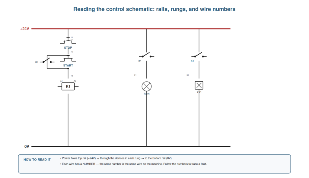
The control schematic is the map of the circuit — the drawing that shows how everything is wired — and learning to read it is perhaps the single most valuable skill in control-circuit troubleshooting. A technician who can read the schematic knows what should happen, can trace the path a fault must lie on, and can follow the wire numbers to the actual wires on the machine. This chapter teaches reading the control schematic in the practical terms a maintenance technician needs, so that the drawing becomes a tool you use to find faults.
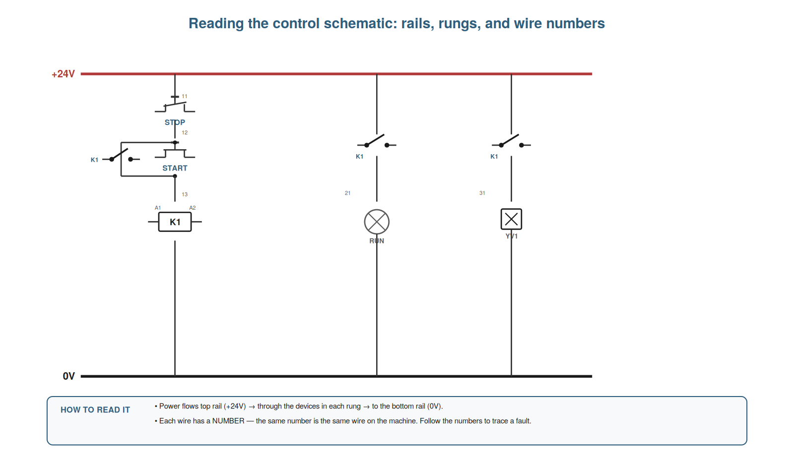
Rails and rungs
The basic structure of a control schematic is the rails and rungs, and understanding this structure lets you see how the circuit works and how current flows through it. The schematic is drawn with two rails — typically the +24V at the top (or one side) and the 0V at the bottom (or other side) — and between them run the rungs, each rung being a path from one rail to the other through some devices. Current flows from the +24V rail, down through the devices in a rung (switches, contacts, a coil or lamp), to the 0V rail, completing the circuit and operating the device. So the schematic shows a ladder of rungs between the two rails, each rung a path current can take. Understanding this — rails supplying the rungs, current flowing rung by rung from +24V to 0V — lets you see how the circuit works: each rung is a little circuit that operates its device when its path is complete. This structure is the key to reading the schematic. Understanding rails and rungs — the +24V and 0V rails with rungs running between them, each rung a path from +24V through devices to 0V — lets you see how the control circuit works, so that you read the schematic as a ladder of rungs where current flows from the positive rail through each rung’s devices to the zero-volt rail, operating the device when the path is complete, which is the fundamental structure of the control schematic and the basis for tracing how the circuit should behave and where a fault must lie.
Following the wire numbers
A crucial practical feature of the schematic is the wire numbers, and understanding how to follow them connects the drawing to the actual wires on the machine — the key to using the schematic for real troubleshooting. Each wire in the schematic has a number, and that same number is marked on the actual wire in the panel (on its ferrule or label). This means the schematic and the machine are linked by the numbers: a wire labelled 14 on the drawing is the wire labelled 14 in the panel. So when you trace a fault on the schematic to a particular wire, you can find that exact wire on the machine by its number, and vice versa — a wire you are measuring in the panel can be located on the drawing by its number. Following the wire numbers is thus how you move between the drawing and the reality, tracing a fault from one to the other. Understanding how to follow the wire numbers — the link between the schematic and the actual wires — lets you use the drawing for real troubleshooting. It reinforces that wire numbers link the schematic to the machine, so you can trace a fault between drawing and reality by the numbers. Understanding how to follow the wire numbers — the numbers that link each wire on the schematic to the same wire marked in the panel — connects the drawing to the actual machine, so that you can trace a fault from the schematic to the exact wire on the machine (and back), which is the key to using the schematic as a real troubleshooting tool: it lets you reason about the fault on the drawing and then find the actual wires and terminals involved by their numbers, moving fluently between the map and the territory that following the wire numbers makes possible.
Seeing what should happen
The deepest value of reading the schematic is seeing what should happen — understanding the intended operation — because this is what lets you recognize what is wrong. By reading the schematic, you can trace the intended operation: press the start button, and this rung energizes that coil, which closes those contacts, which operate these devices; the stop button, wired normally-closed, breaks the circuit when pressed. Understanding this intended sequence — what should happen when — gives you the reference against which to judge the actual behavior. When the machine misbehaves, you compare what is happening to what the schematic says should happen, and the difference points to the fault: if pressing start should energize a coil but does not, the fault is in that rung. So reading the schematic to see what should happen gives you the essential reference for recognizing and locating faults. Understanding how to see what should happen — tracing the intended operation from the schematic — gives you the reference for recognizing what is wrong. It reinforces that reading the schematic reveals the intended operation, which you compare to the actual behavior to locate a fault. Understanding how to see what should happen from the schematic — tracing the intended operation so you know what each button, contact, and coil should do — gives you the essential reference for recognizing and locating faults, so that you can compare the machine’s actual behavior to the schematic’s intended behavior and let the difference point you to the fault, which is the deepest value of reading the schematic: it tells you what a healthy circuit should be doing, without which you cannot recognize what a fault has changed, making the schematic the reference that underlies all reasoned control-circuit troubleshooting.
Cross-references and where things continue
A feature of real schematics worth understanding is cross-referencing — how the drawing shows where a wire or device continues on another part of the diagram — because it lets you follow a circuit across pages. Real control schematics span many pages or sheets, and a wire or the contacts of a relay may appear on a different sheet from where they start. Cross-references handle this: a wire leaving one sheet is marked with a reference to where it continues (the sheet and location it goes to), and a relay’s coil carries a list of where its contacts appear elsewhere. So you can follow a circuit across the drawing by following the cross-references: a wire that seems to end at the edge of a sheet actually continues where its reference points, and a relay’s contacts can be found by its coil’s contact list. Understanding cross-references lets you trace a circuit through a multi-sheet schematic without losing the thread. So understanding cross-references — the markers showing where wires and contacts continue — lets you follow a circuit across the whole drawing. Understanding cross-references and where things continue — the markers on a schematic showing where a wire continues on another sheet and where a relay’s contacts appear — lets you follow a circuit across a multi-sheet drawing, so that you can trace a wire that leaves one sheet to where its reference points and find a relay’s contacts from its coil’s contact list, which keeps you from losing the thread in a real schematic that spans many pages and lets you follow the full circuit across the drawing, an essential skill for reading the real, multi-sheet schematics of actual machines.
Scenario: the schematic that named the wire
A scenario shows the schematic and wire numbers leading straight to a fault. A solenoid would not operate, and rather than probing blindly, the technician read the schematic first. It showed the solenoid fed through a specific rung, with the wire to the solenoid numbered 47. Understanding the intended operation, he saw that a relay contact should close to feed wire 47 when the machine was in a certain state — and it was in that state, so wire 47 should be live. He went to the panel, found the wire labelled 47 by its number, and measured it: 0 volts, though it should have been 24. That localized the fault to the rung feeding wire 47. Following it back by the schematic, he found the relay contact that should have fed it was not closing — the actual fault. Reading the schematic and following the wire number had taken him straight to the fault. This scenario shows the schematic and wire numbers leading directly to a fault. Understanding how to read the schematic and follow the wire numbers let the technician localize the fault to a specific numbered wire and trace it to the cause. It reinforces that reading the schematic and following wire numbers takes you straight from symptom to the faulty part of the circuit. The scenario reinforces reading the schematic: the technician went straight to the fault by reading the intended operation, identifying the wire by its number, measuring it, and tracing back — illustrating how the schematic and its wire numbers turn a blind search into a directed diagnosis that leads from the symptom to the exact wire and thence to the cause, which is the practical power of reading the drawing before reaching for the meter.
Reading PLC I/O on the schematic
A practical schematic-reading skill is understanding how PLC inputs and outputs appear, because on a PLC-based machine much of the circuit connects to PLC I/O and reading it links the wiring to the program. On the schematic, a PLC input is shown as a terminal (with an address, like I0.0) fed by an input device (a sensor or button) — so you can see which physical signal drives which input address. A PLC output is shown as a terminal (with an address, like Q0.0) driving an output device (a relay, valve, or lamp) — so you can see which output address operates which device. Reading these links the physical wiring to the PLC program: a sensor on input I0.0, an output Q0.0 driving a valve. For troubleshooting, this lets you connect a measured signal to its PLC address: if the sensor on I0.0 is switching correctly (measured at the input) but the machine does not respond, the issue may be in the program or the output side, not the input. Understanding how to read PLC I/O on the schematic links the wiring to the program and directs the diagnosis. Understanding how to read PLC I/O on the schematic — inputs shown as addressed terminals fed by input devices, outputs as addressed terminals driving output devices — links the physical wiring to the PLC program, so that you can see which sensor drives which input address and which output operates which device, and connect a measured signal to its address, which lets you localize a fault to the input side, the output side, or (by elimination) the program, an important skill for reading the schematics of the many PLC-based machines and directing the diagnosis accordingly.
The schematic as your map
To close, it helps to see the schematic as the map you troubleshoot by, because this framing captures why reading it is so central. Every diagnosis needs a map: what should happen, how the circuit is wired, which wire is which. The schematic is that map — it shows the intended operation, the rungs and rails, the wire numbers linking drawing to machine. Reading it turns troubleshooting from wandering into navigating: you know where you are, where the fault must be, and how to get to the actual wires. So the schematic is your map, and reading it well is knowing how to navigate the circuit. Understanding the schematic as your map — the drawing you navigate the circuit by — captures why reading it is central to troubleshooting. Understanding the schematic as your map — the drawing showing the intended operation, the rungs and rails, and the wire numbers that let you navigate from the drawing to the actual wires — captures why reading it is so central, so that you approach every fault with the map that tells you what should happen, where the fault must be, and how to reach the real wires involved, which turns troubleshooting from aimless wandering into purposeful navigation and is the deeper reason the schematic is your first tool, before the meter, on every control-circuit fault.