The digital multimeter is your primary troubleshooting tool for 24 volt DC control circuits, and understanding it — particularly its three key functions and the crucial rule about live versus dead measurement — is at the heart of effective troubleshooting. Almost all control-circuit diagnosis is done with the meter, and using it well is what separates confident troubleshooting from guesswork. This chapter covers the digital multimeter and the fundamental principles of using it, so that you wield your primary tool with understanding.
The three functions you need
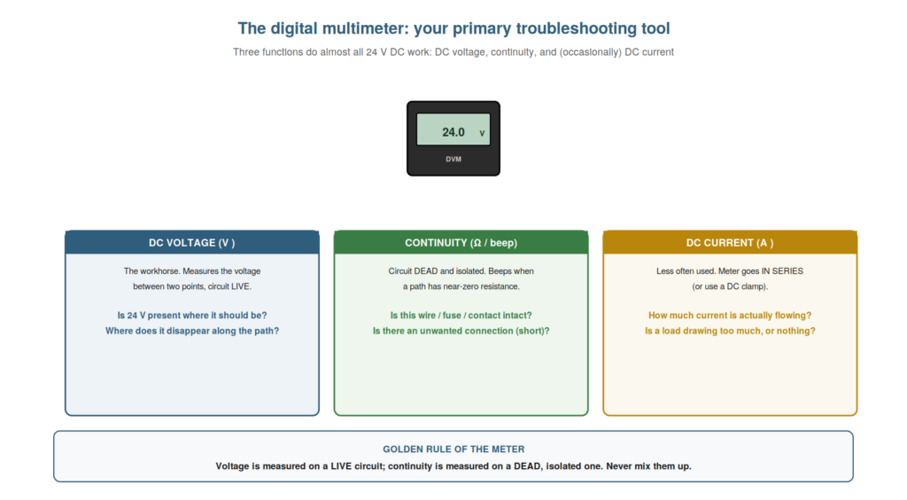
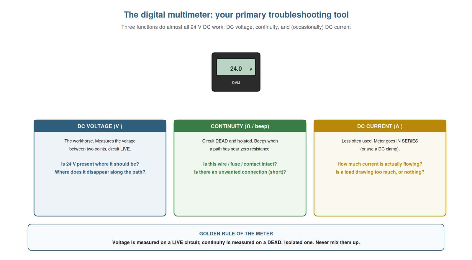
For 24 volt DC control work, three meter functions do almost everything, and understanding what each measures and reveals equips you for nearly all troubleshooting. DC voltage is the workhorse: it measures the voltage between two points on a live circuit, answering ‘is 24 volts present where it should be, and where does it disappear?’ — the core question of most troubleshooting. Continuity (often with a beeper) is measured on a dead, isolated circuit: it tests whether a path has near-zero resistance, answering ‘is this wire, fuse, or contact intact?’ or ‘is there an unwanted connection?’ DC current is used less often: the meter goes in series with the circuit (or a clamp is used), answering ‘how much current is actually flowing?’ — useful for load problems. So the three functions — voltage (live, the workhorse), continuity (dead, for intact paths), and current (occasional, for flow) — cover nearly all control-circuit diagnosis. Understanding what each measures and reveals equips you to choose the right function for each question. Understanding the three functions you need — DC voltage as the live workhorse, continuity for testing intact paths on a dead circuit, and DC current for measuring flow — equips you for nearly all 24 volt DC troubleshooting, so that you know which function answers which question: voltage for ‘is 24 volts present and where does it disappear’, continuity for ‘is this path intact or is there an unwanted connection’, and current for ‘how much is flowing’, which lets you reach for the right meter function for each diagnostic question and covers the great majority of control-circuit troubleshooting with these three essential measurements.
Live versus dead: the golden rule
The single most important rule in using the meter is the distinction between measuring a live circuit and a dead one, and understanding this golden rule prevents mistakes and confusion. DC voltage is measured on a live (energized) circuit — you are measuring the voltage that is present, so the circuit must be powered. Continuity and resistance are measured on a dead (de-energized), isolated circuit — these functions send the meter’s own tiny test current through the path, so any external voltage present would interfere and could damage the meter or give false readings. So the golden rule is: voltage live, continuity dead. Mixing them up causes problems: measuring continuity on a live circuit gives meaningless or misleading readings and risks the meter; expecting a voltage reading on a dead circuit shows nothing because there is no voltage. Understanding and following this rule — voltage on live, continuity on dead — is fundamental to using the meter correctly. It prevents the confusion and errors that come from using the wrong function for the circuit’s state. Understanding the golden rule of live versus dead — that DC voltage is measured on a live, energized circuit while continuity and resistance are measured on a dead, isolated one — is the single most important principle in using the meter, so that you always match the function to the circuit’s state (voltage live, continuity dead), which prevents the meaningless readings, false results, and potential meter damage that come from mixing them up, and ensures that each measurement you take is valid, making this golden rule the foundation of correct and safe meter use in control-circuit troubleshooting.
Setting up and trusting the meter
Practical confidence with the meter includes setting it up correctly and trusting its readings, and understanding these practicalities makes your measurements reliable. Setting up means selecting the right function and range (DC voltage for 24-volt work, continuity for dead-circuit path testing), inserting the leads in the correct sockets (especially important for current, which uses a different socket), and checking the leads are sound (a broken lead gives false readings). Trusting the meter means, once set up correctly, believing its readings and reasoning from them: if it reads 0 volts where you expect 24, there is a break; if it reads 24 where you expect 0, something is energized that should not be. A common beginner error is doubting a correct reading; the discipline is to trust a properly-set-up meter and let its readings guide the diagnosis. Confirming the meter works (reading a known voltage, like the supply) before relying on it builds this trust. So setting up correctly and trusting the readings makes the meter a reliable guide. Understanding how to set up and trust the meter — correct function, range, leads, and confidence in the readings — makes your measurements reliable. Understanding how to set up and trust the meter — selecting the correct function and range, using the right lead sockets, checking the leads are sound, and then trusting a properly-set-up meter’s readings to guide the diagnosis — makes your measurements reliable, so that you take valid readings and reason confidently from them rather than doubting correct results, which is the practical confidence that lets the meter serve as the dependable primary tool it should be, its trusted readings guiding you to the fault when you have set it up correctly and confirmed it works on a known voltage.
Auto-ranging, resolution, and lead care
A few practical meter details are worth understanding — auto-ranging, resolution, and lead care — because they affect the reliability of your measurements. Auto-ranging meters select the range automatically, which is convenient, but understand that the meter needs a moment to settle on the right range, so a reading may flicker briefly before stabilizing. Resolution is how finely the meter reads (the number of digits): enough resolution to distinguish, say, 24.0 from 23.2 volts matters for spotting voltage drops. Lead care is important and often overlooked: the test leads are a common source of false readings — a broken lead or a poor tip contact gives wrong or intermittent readings, so leads should be checked (a continuity test of the leads touched together should read near zero) and kept in good condition. So understanding these details — letting auto-ranging settle, having adequate resolution, and caring for the leads — makes your measurements reliable. Faulty leads especially can mislead a whole diagnosis, so they are worth checking. Understanding auto-ranging, resolution, and lead care — letting the range settle, having the resolution to spot small differences, and keeping sound leads — makes your measurements reliable. Understanding the practical meter details — letting an auto-ranging meter settle on its range, having enough resolution to distinguish small voltage differences like a voltage drop, and caring for the leads that are a common source of false readings — makes your measurements reliable, so that you avoid being misled by a flickering range, catch the small differences that reveal voltage drops, and — importantly — rule out faulty leads (checking them read near zero when touched together), which prevents the frustrating and misleading errors that a broken lead or poor tip contact can introduce into an entire diagnosis.
Scenario: the continuity test that saved the meter
A scenario shows the golden rule preventing a mistake. A technician new to control work was about to check a wire’s continuity to see if it was intact — but the circuit was still live. Remembering the golden rule (continuity is measured dead, isolated; voltage is measured live), he stopped: testing continuity on a live circuit would have given meaningless readings and could have damaged the meter (which sends its own small current for continuity, not expecting external voltage). Instead, he first isolated the circuit, proved it dead with the voltage function, and only then tested continuity — getting a valid reading that found the open wire. Following the golden rule had prevented a mistake and given him a correct result. Had he tested continuity live, he might have damaged the meter and been misled. Understanding the live-versus-dead rule saved both the meter and the diagnosis. This scenario shows the golden rule preventing a meter mistake and giving a valid result. Understanding that continuity is measured dead and isolated led the technician to isolate first, avoiding damage and getting a valid reading. It reinforces that following the golden rule (voltage live, continuity dead) prevents mistakes and ensures valid measurements. The scenario reinforces the meter’s golden rule: the technician avoided damaging his meter and getting misleading readings by remembering that continuity is measured on a dead, isolated circuit, isolating first before testing — illustrating how the fundamental live-versus-dead rule protects both the meter and the diagnosis, ensuring measurements are valid and the meter is not harmed by using the wrong function on a live circuit.
The meter’s input impedance and phantom voltages
A subtle meter nuance worth understanding is input impedance and the phantom voltages it can show, because it explains occasional puzzling readings on high-impedance points. A digital multimeter has a very high input impedance (it draws almost no current to measure voltage), which is normally good — it does not load the circuit — but it can produce misleading ‘phantom’ voltage readings on a floating or high-impedance point: a wire not connected to anything definite can pick up a small induced voltage that the high-impedance meter reads as some voltage, even though the point is not really driven. So you may see a puzzling reading (a few volts, or a fluctuating value) on a disconnected or floating wire that means nothing real. Understanding this prevents confusion: a phantom voltage on a floating point is not a real supply, and a reading that collapses under the slightest load (or does not behave like a solid source) may be phantom. So understanding input impedance and phantom voltages explains and prevents confusion from these misleading readings. Understanding the meter’s input impedance and phantom voltages — the high impedance that avoids loading the circuit but can read a small induced voltage on a floating or high-impedance point — explains occasional puzzling readings, so that when you see an unexpected or fluctuating voltage on a disconnected or floating wire, you recognize it may be a phantom voltage picked up by the high-impedance meter rather than a real supply, which prevents the confusion of chasing a voltage that is not really there and helps you distinguish a solid, driven 24 volts from a meaningless phantom reading on a floating point.
The meter as an extension of your reasoning
To close, it helps to see the meter not as a magic box but as an extension of your reasoning, because this framing captures how to use it well. The meter does not find faults by itself; it answers specific questions you pose — is 24 volts here? is this path intact? — and you reason from the answers. Used well, the meter is the instrument through which your reasoning about the circuit meets reality: you form a question from the schematic and the symptom, the meter answers it, and you reason on. So the meter is an extension of your reasoning, most powerful when you pose clear questions and reason from clear answers, rather than probing aimlessly. Understanding the meter as an extension of your reasoning — answering the questions you pose — captures how to use it well. Understanding the meter as an extension of your reasoning — the instrument that answers the specific questions you pose about the circuit, through which your reasoning meets reality — captures how to use it well, so that you wield the meter by forming clear questions from the schematic and symptom, letting it answer them, and reasoning on from the answers, rather than probing aimlessly, which makes the meter most powerful as the extension of a reasoning mind and is the deeper way to understand your primary troubleshooting tool beyond its individual functions.