Building on the meter’s functions, this chapter covers the practical techniques of measuring voltage, continuity, and current in a control circuit — particularly the powerful voltage-tracing technique of measuring with respect to a reference point — because mastering these measurements is what lets you find faults. Understanding not just what each function does but how to use it to trace and localize a fault turns the meter into a fault-finding instrument. This chapter covers the measurement techniques the troubleshooter relies on.
Voltage tracing from a reference
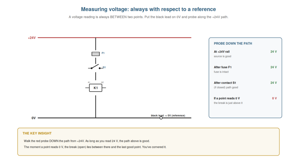
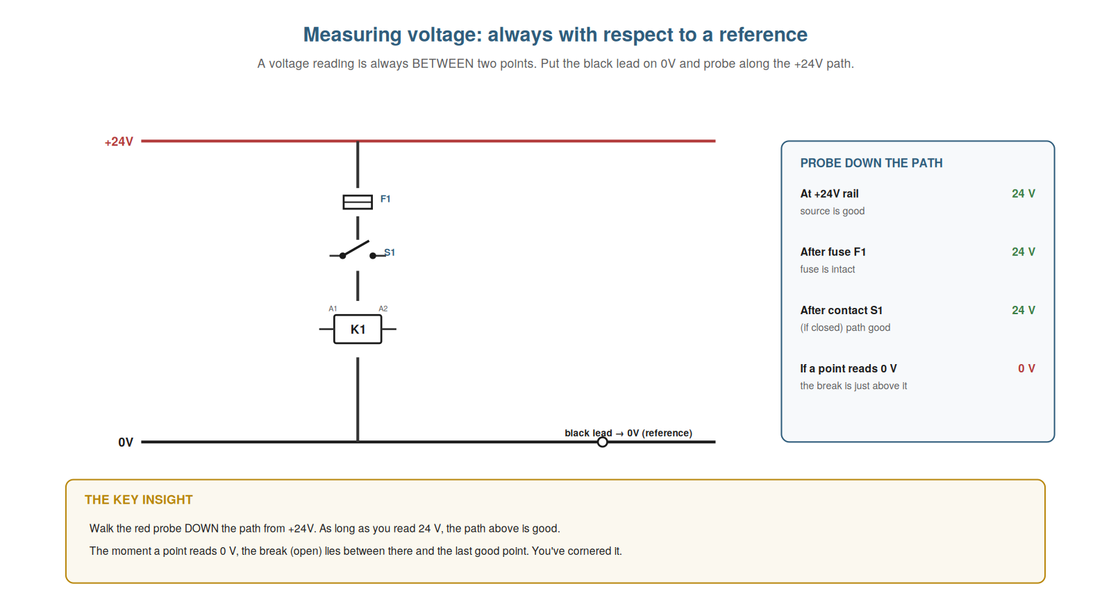
The most powerful voltage measurement technique is tracing with respect to a fixed reference point, and understanding it gives you an efficient way to locate an open. The technique: put the black (reference) lead on a fixed 0V point, and use the red probe to measure the voltage at successive points along the +24V path from the source toward the load. As long as the path is intact, each point reads 24 volts (with respect to the 0V reference). When you reach a point that reads 0 volts, you have passed the break: the open lies between that point and the last point that read 24 volts. So by walking the red probe down the path, you find where 24 volts becomes 0 volts, which localizes the open to that segment. This is powerful because it directly locates the break: you do not have to guess, you measure down the path until the voltage disappears, and the break is right there. Understanding voltage tracing from a reference — walking the probe down the path to find where voltage disappears — gives you an efficient, direct way to locate an open. It reinforces that measuring successive points against a 0V reference locates the open where 24 volts becomes 0 volts. Understanding voltage tracing from a reference — keeping the black lead on a 0V reference and walking the red probe down the +24V path until you find where 24 volts becomes 0 volts — gives you an efficient, direct way to locate an open, so that instead of guessing where the break is, you measure down the path and let the point where the voltage disappears reveal that the open lies between there and the last good point, which is the most powerful and commonly-used voltage technique in control-circuit troubleshooting and the basis for the divide-and-conquer method that finds faults quickly.
Continuity testing done right
Continuity testing is invaluable for checking paths on a dead circuit, and understanding how to do it right — including the essential isolation — makes it reliable and safe. To test continuity correctly, the circuit must be dead (de-energized) and the section you are testing isolated (disconnected at least at one end from the rest of the circuit), so that the meter’s tiny test current flows only through the path you intend to test, not through parallel paths or into a live circuit. With this done, continuity tells you whether a path is intact: a wire, fuse, or contact that is good will beep (near-zero resistance), while an open one will not (infinite resistance). Isolation matters because without it, the meter’s current can find other paths, giving a false ‘good’ reading through a route you did not intend, or the presence of voltage can interfere. So continuity done right — dead circuit, isolated section — reliably tells you whether a specific path is intact. Understanding continuity testing done right — dead, isolated, testing a specific path — makes it a reliable check of whether a path is intact. It reinforces that continuity must be done on a dead, isolated section so the meter tests only the intended path, telling you reliably whether it is intact. Understanding continuity testing done right — on a dead circuit, with the section isolated so the meter’s test current flows only through the intended path — makes it a reliable and safe check of whether a wire, fuse, or contact is intact, so that you avoid the false readings that come from parallel paths or interference and get a trustworthy answer about a specific path’s integrity, which is what makes continuity testing invaluable for confirming opens and checking components on a de-energized circuit, provided you do it right with proper isolation.
Measuring current when you need to
Though used less often, measuring current is sometimes necessary, and understanding when and how to do it completes your measurement toolkit. You measure current when you need to know how much is actually flowing — for instance, to check whether a load is drawing its expected current, whether something is drawing excess (a partial short or overload), or whether current is flowing at all through a path. To measure current, the meter must be in series with the circuit (the current flows through the meter), which means breaking the circuit to insert the meter — more involved than voltage measurement — or, more conveniently, using a DC clamp meter that measures current without breaking the circuit. Because it is more involved, current measurement is reserved for when voltage and continuity have not answered the question, typically for load or excess-current problems. So understanding when and how to measure current — in series or with a clamp, for questions of how much is flowing — completes your measurement toolkit for the occasional current question. Understanding how to measure current when you need to — in series or with a clamp, for questions of how much is flowing — completes your measurement toolkit for the occasions voltage and continuity cannot answer. Understanding how to measure current when you need to — placing the meter in series (breaking the circuit) or using a DC clamp, to answer how much current is actually flowing for load or excess-current problems — completes your measurement toolkit, so that for the occasional question that voltage and continuity cannot answer (is the load drawing its expected current, is something drawing excess, is current flowing at all), you can measure the current, typically reserving this more involved measurement for the load and excess-current problems where knowing the actual current is what the diagnosis requires.
The two-probe voltage-drop measurement
A specific technique worth understanding in more depth is the two-probe voltage-drop measurement, because it is how you directly reveal a high-resistance connection. Instead of referencing 0V, you place the two probes on either side of a single connection — a terminal, a contact, a length of wire — while the circuit is under load, and read the voltage difference across just that connection. A healthy connection drops almost nothing (a few millivolts), so you read near zero; a high-resistance connection drops a significant voltage (tenths of a volt to volts) as the load current flows through its resistance, so you read that drop directly. This isolates the measurement to one connection, telling you precisely whether that connection is the problem. So the two-probe voltage-drop measurement — probes across one connection, under load — directly reveals whether that connection has excess resistance. Understanding this technique lets you check individual connections for the voltage drop that indicates a fault. So understanding the two-probe voltage-drop measurement — reading across one connection under load — directly reveals a high-resistance fault at that connection. Understanding the two-probe voltage-drop measurement — placing the probes on either side of a single connection under load and reading the voltage dropped across just that connection, near zero for a healthy joint and significant for a high-resistance one — lets you directly reveal a high-resistance connection, so that you can check individual terminals, contacts, and wires for the voltage drop that indicates excess resistance, isolating the measurement to one connection and telling you precisely whether it is the culprit, which is the direct and definitive way to find the voltage-drop faults that a continuity test would miss and a 0V-referenced reading would not localize as cleanly.
Scenario: walking the probe to the break
A scenario shows voltage tracing from a reference finding an open directly. A lamp would not light, and the technician used voltage tracing to find the open. Black lead fixed on 0V, he probed down the +24V path to the lamp: at the rail, 24 volts; after the fuse, 24 volts; after the first terminal, 24 volts; after the next contact, 24 volts; at the next terminal — 0 volts. The voltage had disappeared between the contact and that terminal, so the break was right there. Inspecting that segment, he found a broken wire between the contact and the terminal. He had walked the probe down the path and let the point where 24 volts became 0 volts reveal the break exactly. No guessing — the voltage trace pointed straight to the faulty segment. This scenario shows voltage tracing from a reference finding an open directly. Understanding voltage tracing from a 0V reference let the technician walk the probe down the path and find the break where 24 volts became 0 volts. It reinforces that voltage tracing from a reference locates an open directly, at the point voltage disappears. The scenario reinforces voltage tracing: the technician found an open directly by keeping the black lead on 0V and walking the red probe down the path until the voltage disappeared, pinpointing the break to the segment where 24 volts became 0 volts, illustrating how tracing from a fixed reference locates an open without guesswork by revealing exactly where along the path the voltage is lost, the most direct application of the technique.
Using a clamp meter for current
A practical technique worth understanding is using a DC clamp meter for current, because it measures current conveniently without breaking the circuit. The traditional way to measure current — putting the meter in series — requires breaking the circuit to insert the meter, which is inconvenient and not always practical. A DC clamp meter avoids this: its jaws clamp around a single conductor and measure the current flowing through it by sensing the magnetic field, without any electrical connection or breaking the circuit. So you can measure the current in a wire simply by clamping around it, quickly and non-invasively. This is especially useful for checking whether a load is drawing its expected current, or whether excess current is flowing (an overload or partial short), without the disruption of breaking into the circuit. Note it must be a DC-capable clamp (many clamps measure only AC), and it clamps one conductor (not the whole cable, which would cancel out). Understanding the clamp meter gives you a convenient way to measure current. Understanding how to use a DC clamp meter for current — clamping around a single conductor to measure its current by the magnetic field, without breaking the circuit — gives you a convenient, non-invasive way to measure current, so that instead of breaking the circuit to insert the meter in series, you clamp around a wire to read its current quickly, which is especially useful for checking whether a load draws its expected current or whether excess current flows, provided you use a DC-capable clamp around a single conductor, adding a practical and convenient current-measurement technique to your toolkit.
Choosing the right measurement
To close, it helps to emphasize choosing the right measurement for the question, because matching the technique to the question is what makes your measuring effective. Each technique answers a particular question: voltage tracing finds where a live path loses its voltage (an open), continuity confirms whether a dead path is intact, voltage-drop-under-load finds high resistance, current tells how much is flowing. Effective measuring is choosing the technique that answers the question you have: for a dead load, voltage tracing; for a suspected intact-or-not path, continuity; for a weak device, voltage drop; for a flow question, current. So choosing the right measurement — matching technique to question — is what makes measuring effective. Understanding to choose the right measurement — matching the technique to the question — makes your measuring effective. Understanding to choose the right measurement for the question — voltage tracing for an open, continuity for an intact path, voltage drop for high resistance, current for flow — makes your measuring effective, so that rather than applying one technique to everything, you match the measurement to the question you have, which ensures each measurement actually answers what you need to know and is the practical skill of using voltage, continuity, and current well: choosing, each time, the technique that answers the question in front of you.