The whole point of the loop is that the current represents a measurement, and the relationship between the two — the scaling — is what turns milliamps into meaningful engineering units like bar, degrees, or percent. Understanding scaling is essential both for interpreting a loop’s reading and for diagnosing the class of faults where the current is fine but the interpreted value is wrong.
A straight line from current to value
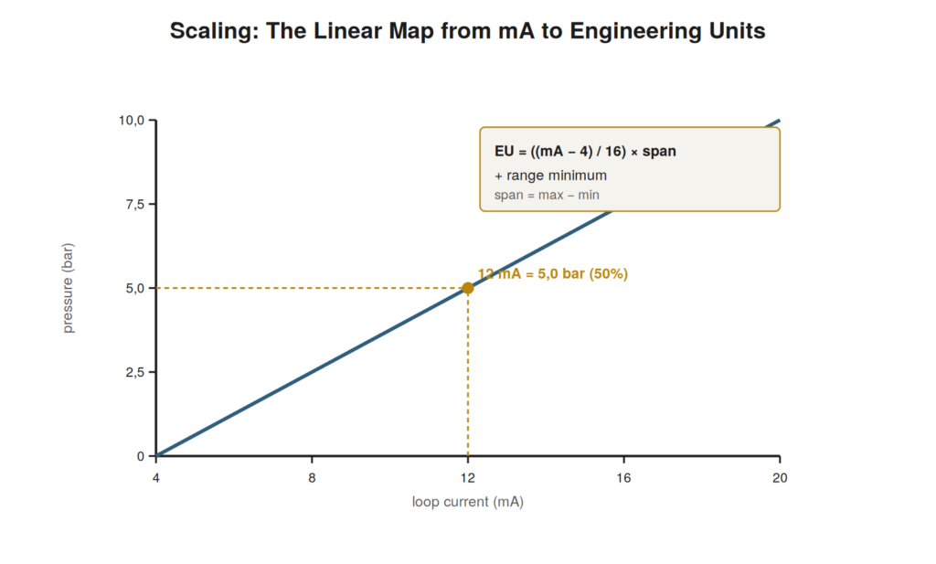
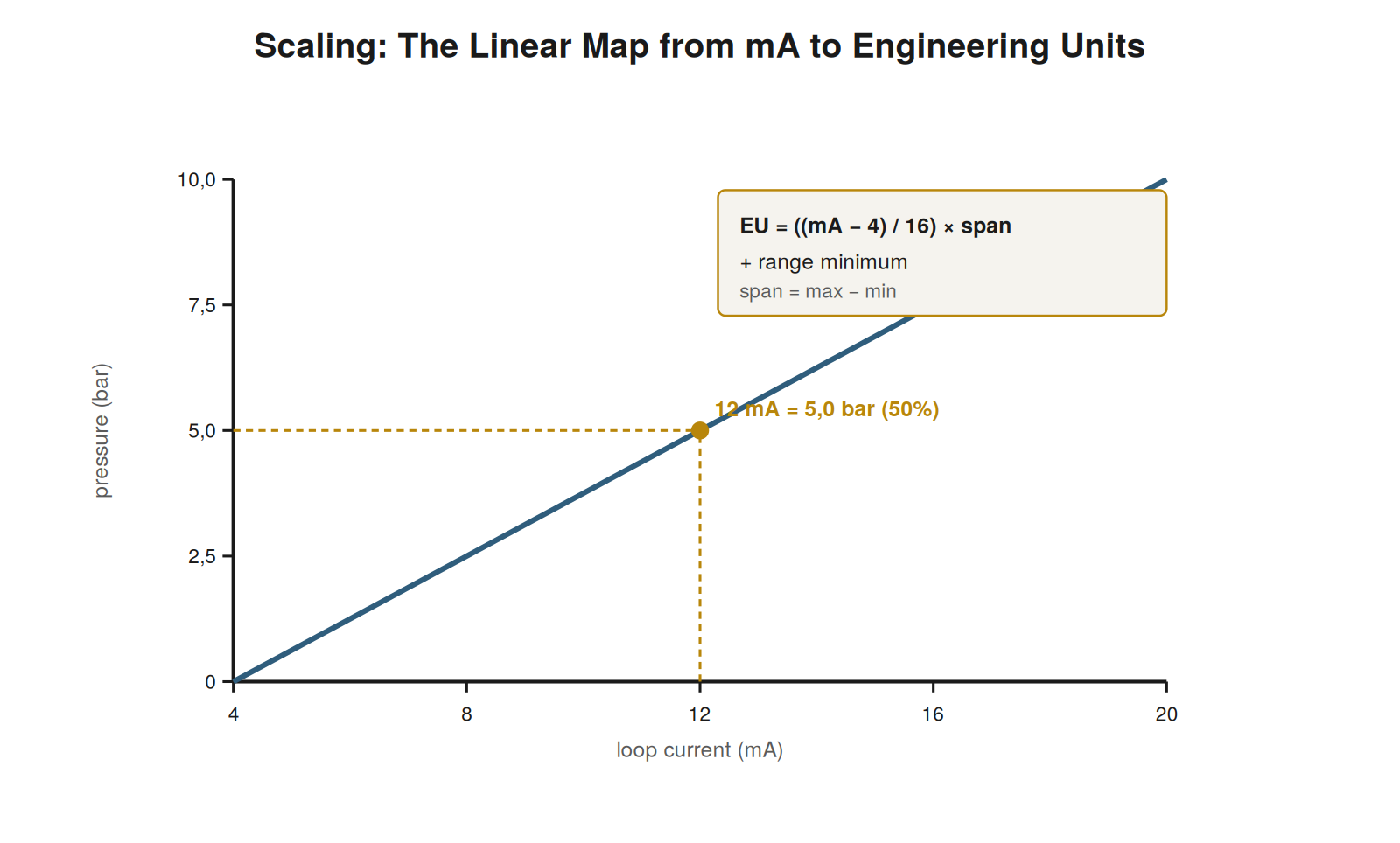
The scaling relationship is a simple straight line: the current from 4 to 20 mA maps linearly onto the measured range from its minimum to its maximum. 4 mA corresponds to the bottom of the range (0% of span), 20 mA to the top (100% of span), and any current in between corresponds to the same proportion of the range. If a pressure transmitter is ranged 0 to 10 bar, then 4 mA is 0 bar, 20 mA is 10 bar, and 12 mA — halfway between 4 and 20 — is 5 bar, halfway up the range. This linear proportionality is the essence of scaling: the fraction of the way the current is between 4 and 20 mA equals the fraction of the way the value is between the range’s minimum and maximum. Understanding the scaling as this straight-line map is the foundation for reading a loop’s value from its current and for the scaling calculations that make the reading precise.
The span and the range
Two terms are central to scaling: the range and the span. The range is the pair of values the loop measures between — for example 0 to 10 bar, or minus 50 to plus 150 degrees — defining what 4 mA and 20 mA mean. The span is the width of the range, the difference between its maximum and minimum — 10 bar in the first example, 200 degrees in the second. The span matters in scaling calculations because the 16 mA of signal range (from 4 to 20) maps onto the full span, so each milliamp represents one-sixteenth of the span. Reading a loop’s range and span from its documentation tells you what its current means: without knowing the range, a current of 12 mA is just a current, but with the range 0 to 10 bar, 12 mA is definitely 5 bar. The range and span are the key parameters that connect the universal 4–20 mA current to the specific engineering units of a particular loop, and reading them is the first step in interpreting any loop’s signal.
Why scaling faults are distinct
A crucial insight for troubleshooting is that scaling is a distinct layer from the loop current, so scaling faults are a distinct class of problem. The loop can carry exactly the correct current — a perfectly healthy 12 mA — while the value shown to the operator is wrong, because the scaling that converts current to engineering units is set up incorrectly. If the control system is configured with the wrong range, the correct current is converted to the wrong value: a 12 mA signal that should read 5 bar might display as some other number if the configured range is wrong. This means a wrong reading does not always mean a wrong current; it can mean correct current but wrong scaling. Recognizing scaling as a separate layer — the current is one thing, its interpretation into a value is another — is essential to troubleshooting, because it directs you to check both whether the current is correct and whether the scaling that interprets it is correct, which are two different investigations with two different fixes.
Seeing the scaling as a graph
It helps to hold the scaling relationship as a mental graph: a straight line with current on one axis and engineering value on the other, running from the point (4 mA, range minimum) to (20 mA, range maximum). Every current maps to a value by reading up to the line and across, and every value maps to a current by reading across to the line and down. This graphical picture makes the relationship intuitive: the line’s slope is the span divided by 16 mA, its position is fixed by the two endpoints, and any point on it relates a current to its value. Seeing scaling as this line clarifies why it is linear (a straight line), why 4 mA gives the minimum and 20 the maximum (the endpoints), and why a current halfway between 4 and 20 gives a value halfway up the range (the midpoint of the line). Whenever the scaling calculation feels abstract, returning to this mental graph — the straight line from (4, min) to (20, max) — makes it concrete and intuitive, and it is the picture behind all the scaling arithmetic.
Scenario: the same current, two different meanings
A scenario highlights why the range matters so much. Two identical loops each carried exactly 12 mA, yet they meant completely different things because they had different ranges. One was a pressure loop ranged 0 to 10 bar, so its 12 mA meant 5 bar (50% of range). The other was a temperature loop ranged 0 to 200 degrees, so its 12 mA meant 100 degrees (also 50%, but of a different range). The identical current — 12 mA — represented 5 bar in one loop and 100 degrees in the other, purely because of the different ranges. This shows that the current alone is meaningless without the range: 12 mA is 50% of whatever the range is, and only the range tells you what 50% corresponds to in engineering units. When interpreting a loop, or configuring the scaling, the range is what gives the current its meaning, and a wrong range makes the correct current mean the wrong thing. This scenario drives home that scaling — the range applied to the current — is what turns a universal milliamp value into a specific, meaningful measurement, and getting the range right is essential to getting the reading right.
Percent as the universal middle language
A useful habit is to think in percent of range as the universal middle language between current and engineering units, because it simplifies scaling reasoning. Any current corresponds to a percent of range — 4 mA is 0%, 12 mA is 50%, 20 mA is 100% — and any percent corresponds to an engineering value via the range. So percent sits in the middle, connecting the universal current to the specific value: convert current to percent (independent of the particular measurement), then percent to value (using the range). This two-step thinking via percent is often easier than a direct current-to-value calculation, and it makes the loop’s behavior intuitive: the loop really carries a percent of range, expressed as a current, interpreted as a value. Thinking in percent also makes cross-loop comparison easy — all loops are at some percent regardless of what they measure — and it clarifies the scaling, since the current-to-percent part is the same for every loop and only the percent-to-value part depends on the range. Adopting percent as the middle language streamlines scaling reasoning and gives a unified way to think about loops carrying different measurements: they all carry a percentage, shown as 4–20 mA, meaning whatever their range makes it.
Scaling as the bridge to meaning
It is worth appreciating scaling as the bridge that gives the loop its meaning, because this perspective clarifies why scaling matters so much. The loop itself carries only a current — a physical quantity with no inherent meaning as a measurement. Scaling is what bridges this current to meaning, mapping it to an engineering value that represents something real: a pressure, a temperature, a level. Without scaling, the current is just a current; with scaling, it is a measurement. This bridging role is why scaling is essential and why scaling errors are so consequential: an error in the bridge makes the correct current mean the wrong thing, corrupting the measurement even though the loop is physically fine. Understanding scaling as the bridge to meaning explains why it is a distinct layer from the loop (the physical current versus its interpretation), why it must be correct for the reading to be meaningful, and why troubleshooting must consider both the current and its scaling. The loop carries the current faithfully, and scaling gives that current its meaning; both must be right for the measurement to be right, and appreciating scaling as the meaning-giving bridge underscores its importance in the whole measurement chain from process to displayed value.
Why scaling lives in the control system
Understanding where scaling happens — typically in the control system — clarifies where scaling faults live and how to fix them. The loop carries the current from field to control system, and it is the control system that applies the scaling, converting the received current to an engineering value for display and use, based on the range configured for that input. So the scaling is a configuration in the control system, separate from the field loop, and a scaling error is a configuration error in the control system, not a fault in the field loop. This is why a scaling fault presents as a correct current but a wrong displayed value: the field loop delivers the right current, and the control system misconverts it due to wrong range configuration. Fixing a scaling fault means correcting the control-system configuration, not touching the field loop. Understanding that scaling lives in the control system — as the configured conversion from current to value — locates scaling faults there and directs their fix to the configuration. It also reinforces the distinction between the loop (delivering the current) and the scaling (interpreting it in the control system), which is why troubleshooting must consider both the field loop and the control-system scaling as separate places a problem can lie.
Scaling errors versus loop faults
A clarifying distinction to hold firmly is between scaling errors and loop faults, because they are diagnosed and fixed completely differently. A loop fault is a problem in the physical loop — the current is wrong or absent due to a broken wire, dead transmitter, lost power, or the like — and it is diagnosed by measuring the current and localizing the physical problem, then fixed by repairing the loop. A scaling error is a problem in the interpretation — the current is correct but converted to the wrong value due to misconfigured scaling — and it is diagnosed by confirming the current is right for the process while the displayed value is wrong, then fixed by correcting the control-system configuration. These are entirely different: one is a physical fault fixed by repair, the other a configuration error fixed by reconfiguration. Confusing them wastes effort — hunting for a physical fault when the current is fine and the problem is scaling, or reconfiguring scaling when the current is actually wrong. Holding the distinction firmly — is the current itself right or wrong for the process? — directs the diagnosis correctly: a wrong current means a loop fault, a correct current with a wrong value means a scaling error. This single question separates the two classes and points each to its appropriate diagnosis and fix, which is why understanding scaling as a distinct layer from the loop is so important to troubleshooting.