Relays are easy to understand physically, but reliable relay circuits still require careful attention to coil drive, contact stress, and transient energy. Coil voltage is a design value.
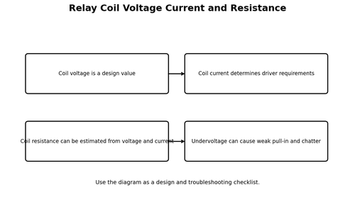
The main ideas are: Coil voltage is a design value. Coil current determines driver requirements. Coil resistance can be estimated from voltage and current. Undervoltage can cause weak pull-in and chatter.
Always separate the coil circuit from the contact circuit in your reasoning. A relay can click correctly while the contacts are wired incorrectly, and the load can be healthy while the coil never receives enough voltage to pull in. Treat those as separate diagnostic branches.
Numbers on a datasheet are meaningful only with their test conditions. Read the small print beside the number before treating it as a design guarantee.
Worked thinking: A 5 V relay coil drawing 70 mA has an effective resistance near 71 ohms during steady DC operation. The example is meant to demonstrate the method, not to replace the ratings and test conditions of the actual part you use.
Useful relationship: R = V / I. Keep units beside every number and calculate the approximate result before measuring the real circuit.
Design view – coil voltage is a design value. Ask which component or connection establishes this behavior and which rating could be exceeded if the load changes. This turns a descriptive fact into a selection rule.
Troubleshooting view – coil current determines driver requirements. Imagine the reading if this condition were missing, too weak, too high, reversed, or intermittent. A useful test is one that separates those possibilities instead of merely producing another number.
Design view – coil resistance can be estimated from voltage and current. Ask which component or connection establishes this behavior and which rating could be exceeded if the load changes. This turns a descriptive fact into a selection rule.
Troubleshooting view – undervoltage can cause weak pull-in and chatter. Imagine the reading if this condition were missing, too weak, too high, reversed, or intermittent. A useful test is one that separates those possibilities instead of merely producing another number.
A switch should be evaluated in both steady state and transition state. ON-state voltage drop creates heat, OFF-state voltage stress can damage the device, and the brief transition between states can be the most stressful period during fast or repetitive switching.
Finish by verifying the real load. A driver that works with an LED may still fail with a relay, motor, solenoid, heater, or long cable because startup current, inductance, wiring resistance, and electrical noise change the conditions dramatically.
Worked Example
A 5 V relay coil drawing 70 mA has an effective resistance near 71 ohms during steady DC operation.
Useful relationship: R = V / I. Write units before substituting values. Use measured values to verify the estimate.
Hands-On Mini-Lab
- Measure coil resistance with power removed.
- Estimate coil current from rated voltage and resistance.
- Energize the coil from a suitable current-limited supply.
- Confirm NO and NC contacts with continuity mode.
- Add the intended coil driver and suppression before connecting the load.
Common Beginner Mistakes
- Driving a relay coil directly from a weak GPIO.
- Leaving out flyback suppression on a DC coil.
- Using an AC contact rating as if it were an equal DC rating.
- Assuming an audible click proves the contacts are healthy.
Fault-Finding Lens
- Verify the actual supply voltage at the load and switching device while the load is commanded ON.
- Measure the control quantity at the device itself: base current for a BJT, VGS for a MOSFET, or coil voltage for a relay.
- Check the load independently when possible so a failed load is not mistaken for a failed driver.
- Inspect protection parts, grounds, connectors, and wiring for open circuits, shorts, reversed polarity, or excessive voltage drop.
- After the repair, repeat the original operating condition and verify current, voltage drop, temperature, and turn-off behavior.
Check Your Understanding
- Explain relay coil voltage current and resistance in your own words.
- Which voltage or current would you measure first to verify this stage?
- What is one failure mode that could make the switch run hot?
- What protection component or design margin is most relevant here?
- How would the circuit behave during controller startup or reset?
Key Points
- Coil voltage is a design value.
- Coil current determines driver requirements.
- Coil resistance can be estimated from voltage and current.
- Undervoltage can cause weak pull-in and chatter.