This component appears so often that learning its normal behavior pays off in nearly every later project. Switches change connectivity.
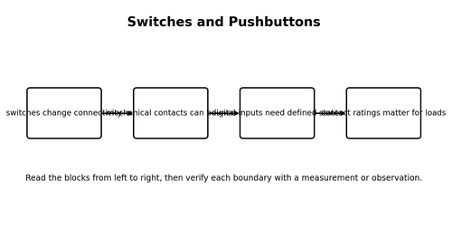
The core ideas are straightforward when separated. Switches change connectivity. Mechanical contacts can bounce. Digital inputs need defined states. Contact ratings matter for loads.
For any unfamiliar component, ask four questions before using it: What job does it perform? Which terminals matter? Which ratings must not be exceeded? What would an open, shorted, reversed, or wrong-value failure look like? That checklist is more useful than memorizing a catalog number.
On the bench, the most valuable habit is to predict first and measure second. The gap between prediction and measurement is where learning happens. In practical work, this means you should be able to describe what you expect before you connect power.
A concrete example makes the idea easier to test. A pushbutton to ground with a pull-up resistor gives a stable HIGH released and LOW pressed. Do not treat the numbers in an example as universal values; use them to learn the method, then check the ratings and datasheet for the actual parts on your bench.
Focus on this point: switches change connectivity. Ask what you could measure to prove that statement in a real circuit. If the expected behavior is present, move to the next block. If it is absent, stay at that stage until the reason is understood.
The phrase “mechanical contacts can bounce” also has a troubleshooting meaning. Consider the failure modes that would make the quantity too high, too low, stuck, noisy, or intermittent. Learning normal behavior and failure behavior together makes the concept far easier to remember.
Focus on this point: digital inputs need defined states. Ask what you could measure to prove that statement in a real circuit. If the expected behavior is present, move to the next block. If it is absent, stay at that stage until the reason is understood.
The phrase “contact ratings matter for loads” also has a troubleshooting meaning. Consider the failure modes that would make the quantity too high, too low, stuck, noisy, or intermittent. Learning normal behavior and failure behavior together makes the concept far easier to remember.
Do not chase precision before you have correctness. First confirm polarity, connectivity, supply voltage, approximate current, and the correct component value. Once the circuit behaves in the right direction, smaller effects such as tolerance, temperature, noise, and measurement loading become worth investigating.
One final bench habit is to keep a last-known-good state. A quick photo, sketch, or table of expected voltages gives you a reference after later changes. This simple habit turns many future faults into comparisons instead of mysteries.
Worked Example
A pushbutton to ground with a pull-up resistor gives a stable HIGH released and LOW pressed.
Hands-On Mini-Lab
- Find the symbol, pinout, and key ratings for a representative part.
- Measure a loose component with the appropriate meter mode if possible.
- Build the simplest circuit that demonstrates its main function.
- Measure the input, output, and one important internal node or voltage drop.
- Create one harmless fault and observe how the symptoms change.
Common Beginner Mistakes
- Replacing a failed part without asking why it failed.
- Guessing a pinout from package shape.
- Ignoring voltage current or power ratings.
- Condemning a part from one ambiguous in-circuit reading.
Fault-Finding Lens
- Start by verifying the power source and the actual supply voltage at the stage you are testing.
- Check the physical connections and polarity before assuming a semiconductor or IC has failed.
- Use the chapter model to find the last point that behaves normally and the first point that does not.
- If the result is ambiguous in circuit, isolate the stage or component and repeat the test with a known reference.
- After correction, reproduce the original operating condition and confirm that current, voltage, temperature, and function remain normal.
Check Your Understanding
- Explain switches and pushbuttons in your own words without using the diagram.
- Which measurement would give the quickest evidence that this circuit or concept is behaving normally?
- Name one beginner mistake that could create a misleading symptom.
- What would you test next if the measured value were much higher or lower than expected?
- How could you demonstrate the key idea with a safe low-voltage experiment?
Key Points
- Switches change connectivity.
- Mechanical contacts can bounce.
- Digital inputs need defined states.
- Contact ratings matter for loads.