What an Industrial Encoder Actually Does
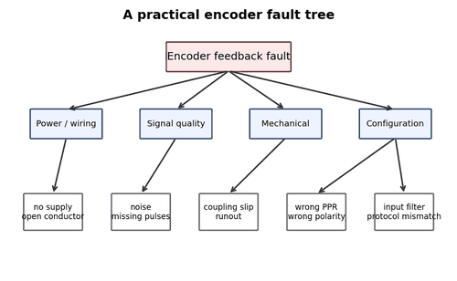
An encoder converts mechanical motion into electrical information that a controller can count, compare, or decode. The machine may use that information for speed regulation, positioning, synchronization, cut length, registration, or motion feedback. Troubleshooting becomes much easier when you separate the problem into three layers: mechanical motion at the shaft, electrical signal generation inside the encoder, and correct interpretation by the receiving device.
What to Check
- Confirm what motion the encoder is intended to measure.
- Identify whether the machine needs speed, direction, position, or all three.
- Find the receiving device: PLC high-speed counter, drive, servo amplifier, motion controller, or dedicated display.
- Write down the expected pulses per revolution or absolute resolution before testing.
Diagnostic Sequence
- Observe the mechanical shaft while the machine jogs slowly.
- Verify encoder supply voltage at the encoder connector, not only in the cabinet.
- Check whether the receiving device shows changing counts or feedback.
- If counts change but the machine value is wrong, investigate scaling/configuration before replacing hardware.
Common Mistakes
- Replacing the encoder before checking the coupling.
- Testing only in the electrical cabinet while the fault is caused by the machine shaft.
- Assuming that any pulse train means the encoder is healthy.
Field Rule: Always prove motion, power, signal, and interpretation as four separate facts.
Incremental vs. Absolute Feedback
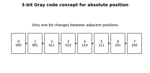
Incremental encoders report change. Their outputs generate pulses as the shaft moves, so the controller builds position by counting. Absolute encoders report a position code that corresponds to the shaft angle or linear location. This difference controls what happens after power loss: incremental position is normally lost unless the system re-homes; absolute position can often be read immediately after startup.
What to Check
- Look for A/B/Z or A+/A-/B+/B- terminals: these strongly suggest incremental feedback.
- Look for SSI, BiSS, EnDat, Hiperface, CANopen, EtherCAT, PROFINET, or another bus/interface name: these suggest absolute or smart feedback.
- Check whether the machine performs a homing cycle after power-up.
Diagnostic Sequence
- For incremental systems, verify count direction and index operation.
- For absolute systems, compare the raw position word with physical motion.
- Check whether a replacement encoder uses the same resolution, code format, and multiturn capability.
Common Mistakes
- Replacing an absolute encoder with a mechanically similar incremental model.
- Ignoring position presets or electronic zero after replacement.
- Assuming an encoder is absolute merely because it has many wires.
Field Rule: First identify the feedback type; every later test depends on it.
Optical Encoder Construction
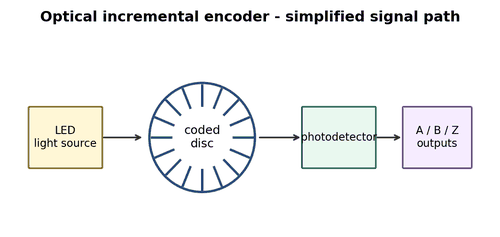
Optical encoders typically use a light source, a patterned disc, and photodetectors. As the disc rotates, alternating transparent and opaque regions modulate the light. Electronics convert these transitions into clean digital channels. Contamination, bearing wear, disc damage, condensation, or excessive vibration can disturb this optical path even when the external cable looks perfect.
What to Check
- Inspect the enclosure for cracked seals, missing gland compression, oil ingress, and washdown damage.
- Listen for rough bearings while rotating the shaft by hand with the machine safely isolated.
- Check for axial movement that could shift the code disc relative to the sensor.
Diagnostic Sequence
- If the encoder fails only hot, compare operation before and after warm-up.
- If pulses disappear at one angle repeatedly, suspect internal disc or bearing issues.
- If the unit was exposed to coolant or water, inspect connector pins and sealing before blaming PLC electronics.
Common Mistakes
- Opening a sealed encoder that is not designed to be serviced.
- Using compressed air aggressively and pushing contamination into the housing.
- Ignoring mechanical vibration because electrical signals look correct at low speed.
Field Rule: Optical encoders are precision instruments; environmental and bearing problems can become signal problems.
Magnetic Encoder Construction
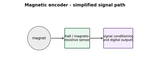
Magnetic encoders sense a rotating magnetic field instead of shining light through a disc. They are often tolerant of dust and oil and can fit compact or hollow-shaft designs. They still depend on correct magnet distance, alignment, supply, electronics, and electromagnetic environment. A loose target magnet can create position errors that appear to be software faults.
What to Check
- Verify the magnetic target or rotor is secure.
- Check axial gap and centering against the installation drawing.
- Inspect nearby strong magnetic fields, motors, brakes, and welding return paths.
Diagnostic Sequence
- Slowly rotate through 360 degrees and look for a repeatable error zone.
- Compare error at low and high speed.
- Check the encoder status word if the device reports field strength or magnet quality.
Common Mistakes
- Assuming magnetic means immune to all contamination and interference.
- Reusing a target magnet with an incompatible sensor body.
- Ignoring axial gap after mechanical service.
Field Rule: Treat magnet position as part of the encoder assembly, not as a separate mechanical detail.
Resolution, PPR, CPR, Lines, and Counts
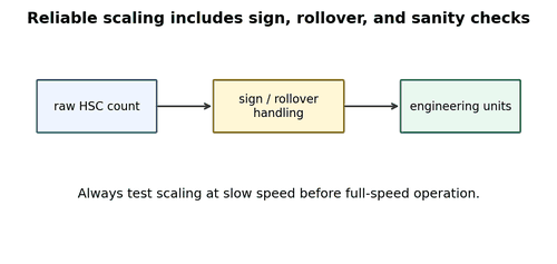
Encoder specifications use several terms that are easily mixed up. PPR may mean pulses per revolution. “Lines” often means optical cycles per revolution. A quadrature counter can count each rising and falling edge of A and B, creating four counts per line. Manufacturers and controller manuals do not always use the same vocabulary, so troubleshooting should rely on exact signal behavior and configured counts rather than labels alone.
What to Check
- Read the encoder label and datasheet.
- Check whether the PLC high-speed counter is configured for x1, x2, or x4 quadrature.
- Compare one physical revolution with the change in raw count.
Diagnostic Sequence
- Mark the shaft and rotate exactly one revolution at low speed.
- Record the raw count change.
- If the measured change differs by exactly 2× or 4×, inspect quadrature counting mode before changing scaling.
Common Mistakes
- Entering 1024 when the controller actually counts 4096 edges.
- Confusing mechanical gearbox ratio with encoder resolution.
- Using rounded diameter values for linear scaling when precision matters.
Field Rule: Prove counts per mechanical revolution with a controlled test.
Speed Feedback from Pulses
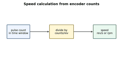
Speed is normally calculated by counting encoder transitions during a time window, or by measuring the period between transitions. High-speed motion produces many pulses and gives stable averages. Very low speed may require period measurement because only a few counts arrive in each sample. A speed display that oscillates does not automatically mean the encoder is bad; the calculation method, update interval, and pulse density matter.
What to Check
- Compare raw pulse frequency with expected mechanical speed.
- Note whether instability appears only near zero speed.
- Check the controller averaging or sample period.
Diagnostic Sequence
- Use frequency mode on a meter or oscilloscope if available.
- Calculate expected frequency from rpm and counts per revolution.
- If the raw frequency is stable but displayed rpm hunts, investigate software scaling and filtering.
Common Mistakes
- Replacing an encoder because a poorly filtered display flickers.
- Using a long averaging window in a fast control loop.
- Ignoring gear ratio between encoder shaft and actual load.
Field Rule: Separate raw pulse stability from the way software converts pulses into speed.
Position Feedback from Counts
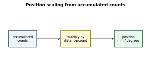
Incremental position is an accumulated count. The controller adds or subtracts counts according to direction, then multiplies by a scale factor to obtain millimetres, degrees, metres, or another engineering unit. Position faults can come from lost pulses, false pulses, reversed direction, mechanical slip, rollover, incorrect scaling, or a missed reference event.
What to Check
- Compare raw count with scaled position.
- Jog equal distances forward and backward and look for repeatability.
- Check whether position returns to the same raw count after a round trip.
Diagnostic Sequence
- If raw count does not repeat, investigate signal loss or mechanical slip.
- If raw count repeats but engineering value is wrong, inspect scale and offsets.
- If only direction is wrong, check A/B phase or direction configuration.
Common Mistakes
- Resetting the position repeatedly instead of finding lost counts.
- Changing scale to hide a mechanical ratio problem.
- Ignoring counter rollover in long-travel applications.
Field Rule: Raw count is your most useful truth signal when debugging incremental position.
A Safe Troubleshooting Mindset
Encoder faults often occur on moving machinery. Testing may tempt technicians to reach near couplings, open guards, or probe terminals while a drive is energized. The diagnostic goal never justifies bypassing lockout procedures or safety circuits. Plan tests so the machine can move at a controlled safe speed, use remote measurements where practical, and follow site procedures for energized work.
What to Check
- Identify pinch points, rotating shafts, stored energy, and unexpected automatic restart risks.
- Know which measurements require power and which can be completed under isolation.
- Use properly rated instruments and insulated probes.
Diagnostic Sequence
- Perform mechanical inspection under lockout/tagout unless the procedure explicitly allows otherwise.
- Use slow jog or maintenance mode for live signal tests.
- Keep loose clothing, test leads, and oscilloscope grounds away from rotating parts.
Common Mistakes
- Holding a meter while standing in the machine envelope.
- Defeating guards to get a better view of the coupling.
- Using an earth-referenced oscilloscope incorrectly on non-isolated circuits.
Field Rule: A good encoder diagnosis returns the machine to service without creating a new hazard.