Channel A: The Basic Pulse Train
Channel A is the simplest evidence that an incremental encoder is producing motion information. At constant speed, the pulse frequency should be steady. Amplitude should remain within the receiving input specification, and edges should be reasonably clean. A dead A channel may be caused by loss of power, a broken conductor, failed output stage, wrong common reference, or incompatible input type.
What to Check
- Measure supply first.
- Check A at the encoder connector and again at the controller.
- Compare frequency at slow and normal speed.
Diagnostic Sequence
- If A exists at the encoder but not at the PLC, troubleshoot the cable and terminals.
- If A is present at the PLC terminal but the HSC does not count, inspect input configuration.
- If A amplitude collapses with cable connected, check loading or short circuits.
Common Mistakes
- Measuring only with the wire disconnected and missing a loaded-circuit fault.
- Using DC voltage alone to judge a fast pulse train.
- Assuming a steady mid-scale meter value means a bad signal.
Field Rule: A pulse train must be verified at the receiver under normal load.
Quadrature: A and B Determine Direction
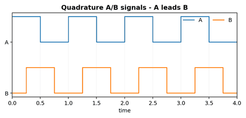
Quadrature encoders use two pulse trains offset by approximately 90 electrical degrees. The channel that changes first determines direction. The controller also gains more count transitions than a single-channel encoder. If A and B are swapped, position may run backward. If one channel is missing, direction and x4 counting can fail while a basic frequency test still looks acceptable.
What to Check
- Scope A and B together.
- Verify both channels have similar amplitude and duty cycle.
- Check which channel leads during known clockwise motion.
Diagnostic Sequence
- Jog clockwise and capture A/B.
- Jog counter-clockwise and confirm the lead/lag reverses.
- If direction is opposite to expectation, correct wiring or configuration according to the machine standard.
Common Mistakes
- Swapping wires without documenting the original state.
- Judging phase relationship with a one-channel meter.
- Ignoring the B channel because the speed display still works.
Field Rule: For direction problems, observe A and B simultaneously.
Clockwise and Counter-Clockwise Phase
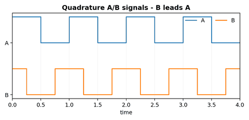
There is no universal promise that “A leading B means clockwise” for every installed machine because clockwise depends on the viewing end and mechanical orientation. What matters is consistency: choose the machine-defined positive direction, record the expected phase relationship, and configure the controller accordingly.
What to Check
- Find the machine drawing or commissioning note that defines positive motion.
- Observe the shaft from the same reference side each time.
- Record the controller sign when jogging in both directions.
Diagnostic Sequence
- Use a two-channel scope or logic analyser.
- Verify phase lead at slow speed where edges are easy to see.
- Check that the software count sign matches the physical positive direction.
Common Mistakes
- Using “clockwise” without specifying viewing direction.
- Changing both wiring and software sign at the same time.
- Assuming a new encoder has the same shaft orientation as the old one.
Field Rule: Define positive motion first; then make the electrical phase and software sign agree.
The Z or Index Pulse
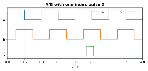
The Z channel, often called index or reference, usually produces one pulse per revolution. Machines use it to establish a repeatable angular reference, refine homing, verify revolutions, or detect a known mark. A machine can run normally for long periods with a failed Z channel and then suddenly fail only during homing or startup.
What to Check
- Determine whether the control program actually uses Z.
- Check index width and polarity in the datasheet.
- Verify the Z pulse appears once per mechanical revolution.
Diagnostic Sequence
- Trigger the oscilloscope on Z while viewing A or B.
- Rotate slowly through multiple revolutions to prove consistency.
- If homing is inconsistent, compare sensor home signal and Z timing.
Common Mistakes
- Replacing limit sensors when the missing event is encoder index.
- Assuming Z should remain high for a large shaft angle.
- Expecting Z at the same physical angle after an encoder replacement without alignment.
Field Rule: When a machine fails only during homing, inspect the index path early.
Duty Cycle and Pulse Symmetry
Ideal A and B channels often appear close to 50% duty cycle, but the exact allowable range depends on the encoder and receiver. Severe duty-cycle distortion can reduce noise margin and may cause missed counts at high frequency. Mechanical eccentricity, optical contamination, internal electronics, cable loading, or unsuitable pull-up resistors can change the observed waveform.
What to Check
- Measure high time and low time on both channels.
- Compare near the encoder and at the receiver.
- Repeat at low and high speed.
Diagnostic Sequence
- If the waveform is clean near the encoder but distorted at the PLC, focus on cable, receiver, termination, and loading.
- If distortion is present at the encoder connector, suspect encoder or supply quality.
- Check whether the input uses a Schmitt trigger or threshold suitable for the signal standard.
Common Mistakes
- Demanding perfect 50/50 waveforms without checking specifications.
- Ignoring duty distortion because the meter still reads the right frequency.
- Using an excessively strong pull-up on an open-collector output.
Field Rule: Signal shape becomes more important as speed and cable length increase.
Missing Pulses
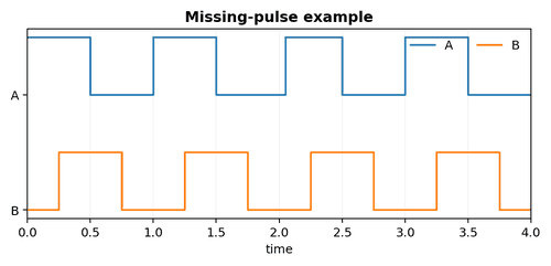
A missing pulse subtracts position from an incremental count. A single lost transition may be invisible on a speed display yet create cumulative position drift. Causes include marginal signal amplitude, cable faults that open under motion, dirty optical components, excessive frequency for the input, or poor shielding near VFD cables.
What to Check
- Ask whether error accumulates with travel or speed.
- Compare commanded movement with raw count after repeated cycles.
- Capture long oscilloscope records or use a high-speed counter diagnostic to look for dropouts.
Diagnostic Sequence
- Reduce speed. If the fault disappears, check input frequency limits and signal integrity.
- Temporarily route a known-good cable away from power conductors.
- Inspect coupling and shaft slip before assuming the pulse is electrically missing.
Common Mistakes
- Looking only at a few clean pulses and declaring the signal good.
- Ignoring intermittent connectors because continuity passes while stationary.
- Masking drift with repeated software re-zero.
Field Rule: Cumulative position loss requires a test long enough to catch rare events.
False Pulses and Double Counts
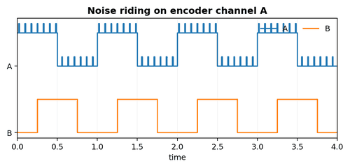
Noise can create extra threshold crossings that the controller interprets as encoder edges. The result may be position gaining counts instead of losing them, or jitter while the shaft is stationary. Fast drives, contactors, poorly bonded shields, long parallel cable runs, and weak single-ended signals are common contributors.
What to Check
- Watch raw counts with the shaft completely stationary.
- Switch nearby drives or contactors and see whether counts jump.
- Scope at the receiving end with enough bandwidth to catch narrow spikes.
Diagnostic Sequence
- If counts change while mechanically stopped, disconnect the encoder signal at the receiver and observe the input state.
- Improve shielding, routing, grounding, and differential reception rather than relying only on software filters.
- Use appropriate input filtering only after confirming it will not reject legitimate high-speed pulses.
Common Mistakes
- Adding a large software debounce that breaks high-speed counting.
- Grounding a shield with a long pigtail in a high-frequency environment.
- Running encoder cable in the same duct as motor output cable.
Field Rule: Counts that change at zero speed are a strong clue for electrical noise or input configuration.
Signal Frequency Limits
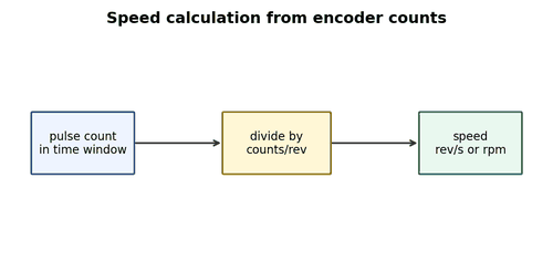
Every encoder output, cable, receiver, PLC high-speed counter, and software task has a maximum usable frequency. A system may work perfectly during jog and fail only at production speed. Calculate expected maximum pulse frequency before replacing components, and remember that quadrature edge counting can multiply internal count rate.
What to Check
- Find maximum mechanical rpm.
- Find encoder cycles or pulses per revolution.
- Find the controller input frequency limit and required minimum pulse width.
Diagnostic Sequence
- Calculate the expected frequency at maximum speed.
- Check the waveform at the receiving end at production speed.
- Compare frequency and rise time with the receiver specification.
Common Mistakes
- Testing only at slow maintenance speed.
- Using a standard PLC input instead of a high-speed counter.
- Confusing pulse frequency with x4 internal count rate.
Field Rule: A correct low-speed signal can still be unusable at full speed.