TTL, HTL, and Logic-Level Compatibility
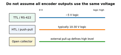
Industrial encoders commonly use low-voltage logic around 5 V, higher-voltage logic such as 10-30 V HTL, or other interface-specific levels. The receiving electronics must match. A 5 V differential encoder connected to a 24 V digital input may not reach the input threshold; a 24 V output connected to a 5 V receiver can damage electronics.
What to Check
- Read encoder output type, not just supply voltage.
- Read PLC or drive input threshold and maximum voltage.
- Confirm whether the signal is single-ended or differential.
Diagnostic Sequence
- Measure high and low levels under load.
- Check that the receiver recognizes both states with margin.
- Use the correct line receiver or interface module when level conversion is required.
Common Mistakes
- Assuming a 24 V powered encoder always outputs 24 V pulses.
- Assuming a 5 V output is safe for every high-speed input.
- Using resistor dividers without checking edge speed and input current.
Field Rule: Match output standard to input standard before troubleshooting software.
RS-422 Differential Line Driver
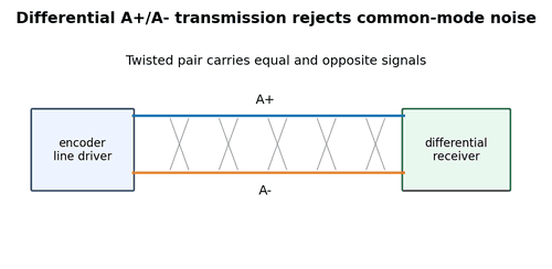
Differential encoders send complementary pairs such as A+ and A-, B+ and B-, and often Z+ and Z-. The receiver reacts to the voltage difference between each pair, which provides strong immunity to noise picked up equally on both conductors. Twisted pairs and proper termination are essential at high speed or long cable length.
What to Check
- Confirm each signal pair is correctly paired and twisted.
- Check whether the receiving device provides termination internally.
- Inspect A+ versus A- with a differential probe or two channels used safely.
Diagnostic Sequence
- Measure both conductors rather than treating A- as 0 V.
- If one conductor is open, the receiver may work intermittently at low speed but fail in noise.
- Check for pair reversal after cable repairs.
Common Mistakes
- Connecting A- to 0 V because it looks like “negative.”
- Splitting a differential pair across different cable pairs.
- Adding termination blindly without checking the encoder driver rating.
Field Rule: In differential signaling, the pair is the signal.
Open-Collector Outputs
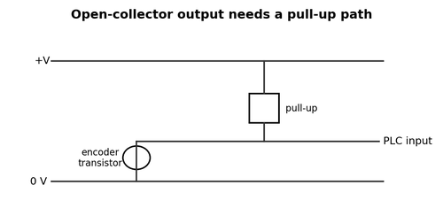
An open-collector or open-drain output usually pulls the signal low but does not actively drive it high. A pull-up resistor or compatible input circuit provides the high state. Without that pull-up, the signal can float. With an unsuitable resistor, rise time may become too slow or output current may be excessive.
What to Check
- Find the required pull-up voltage and resistor range.
- Check whether the PLC input already contains a pull-up.
- Measure signal high level and rise time at normal speed.
Diagnostic Sequence
- If the output pulls low correctly but never rises, inspect the pull-up path.
- If rise time is slow, calculate RC effects from cable capacitance and pull-up resistance.
- Confirm output current does not exceed the encoder transistor rating.
Common Mistakes
- Treating open collector like push-pull.
- Using a very large pull-up on long high-capacitance cable.
- Using a very small pull-up that overloads the transistor.
Field Rule: Open-collector troubleshooting always includes the external current path.
Push-Pull Outputs
Push-pull outputs actively drive both high and low states, giving faster edges and stronger noise margins than many passive pull-up arrangements. They still require compatible voltage, common reference, and input current. A partial short can make one transition strong and the other weak.
What to Check
- Measure both high and low levels.
- Compare A and B amplitude under load.
- Check for heating or unusually low resistance on signal conductors.
Diagnostic Sequence
- Disconnect the receiver only if the manufacturer allows no-load testing, then compare loaded and unloaded levels.
- If voltage improves dramatically when unloaded, investigate receiver compatibility and cable shorts.
- Use an oscilloscope to check edge speed at production frequency.
Common Mistakes
- Assuming push-pull means differential.
- Shorting two push-pull outputs together.
- Ignoring shared 0 V reference on single-ended signals.
Field Rule: Strong output drive does not eliminate the need for correct interface matching.
PNP, NPN, Sourcing, and Sinking
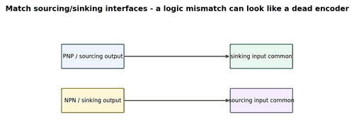
Some industrial encoder outputs are described using PNP/NPN or sourcing/sinking language familiar from sensors. The important question is current direction and the input common arrangement. A sourcing output expects a sinking input path; a sinking output expects a sourcing path. A mismatch can leave the input permanently high, permanently low, or weakly floating.
What to Check
- Identify the output transistor type.
- Identify input common polarity.
- Trace current path on the wiring diagram.
Diagnostic Sequence
- Test one channel slowly and observe input LED plus raw HSC status.
- Measure voltage from signal to the correct common.
- If uncertain, use the manufacturer connection example for the exact module.
Common Mistakes
- Choosing wiring by wire color alone.
- Changing input common without checking other channels on the same group.
- Assuming PNP/NPN labels apply identically to every differential encoder.
Field Rule: Draw the current path; the correct sourcing/sinking relationship becomes obvious.
Encoder Supply Voltage and Brownouts
An encoder can receive nominal voltage in the cabinet but suffer voltage drop at the machine during startup, brake release, or other load changes. Brownouts can reset absolute encoders, distort incremental output amplitude, or create brief loss of feedback that appears as a drive fault.
What to Check
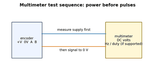
- Measure at the encoder connector while the machine is moving.
- Check both voltage and 0 V return drop.
- Observe supply during contactor pickup, brake operation, and drive acceleration.
Diagnostic Sequence
- Use min/max capture on a meter for slower dips.
- Use an oscilloscope for short transients.
- Inspect common terminals, connector pins, fuse holders, and long small-gauge conductors.
Common Mistakes
- Measuring only at the power supply output.
- Ignoring the return conductor.
- Increasing supply voltage without checking encoder limits.
Field Rule: Power quality must be verified at the load during the fault condition.
0 V Reference Problems
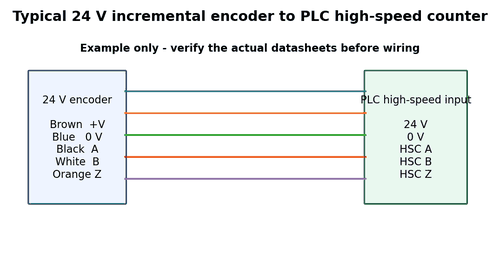
Single-ended encoder signals are interpreted relative to a reference, normally 0 V. A loose return connection can make all channels appear noisy or shift thresholds unpredictably. The signal conductor may test perfectly for continuity while the shared reference is the actual fault.
What to Check
- Measure voltage drop between encoder 0 V and receiver 0 V under operation.
- Inspect shared terminal blocks and connector commons.
- Look for corrosion on low-current return contacts.
Diagnostic Sequence
- Temporarily measure signal and supply with the same reference point.
- If all channels fail together, prioritize common supply/reference faults.
- Check whether shield was incorrectly used as signal 0 V.
Common Mistakes
- Testing only A and B wires.
- Assuming 0 V is identical everywhere in a large machine.
- Bonding signal 0 V to protective earth at random points.
Field Rule: When multiple channels fail together, search for what they share.
Input Threshold and Hysteresis
Digital inputs switch state when voltage crosses internal thresholds. Hysteresis prevents chatter around the switching point. If an encoder high level is marginal or a low level does not fall far enough, noise can create multiple transitions. This is especially common when interfaces are mixed or long cables slow the edges.
What to Check
- Find the guaranteed ON and OFF thresholds, not only nominal voltage.
- Measure actual high/low at the receiver.
- Check edge rise/fall time if the frequency is high.
Diagnostic Sequence
- Compare worst-case levels with guaranteed thresholds.
- If margin is small, correct the interface rather than relying on luck.
- Check whether the HSC has selectable input level or filter modes.
Common Mistakes
- Using an average DC meter reading as threshold evidence.
- Assuming an LED means the high-speed electronics see the same state.
- Ignoring temperature effects on marginal levels.
Field Rule: Reliable counting requires voltage margin, not just occasional threshold crossing.