Coupling Alignment
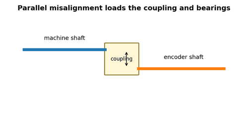
Encoders mounted with flexible couplings tolerate limited misalignment, not unlimited misalignment. Parallel or angular error produces cyclic forces that wear bearings, loosen set screws, and modulate the measured motion. A coupling can look intact while slipping under acceleration.
What to Check
- Inspect alignment after any motor, gearbox, or encoder replacement.
- Check coupling element condition and set-screw witness marks.
- Verify the encoder shaft is not forced sideways when bolts are tightened.
Diagnostic Sequence
- Isolate the machine and mark both coupling hubs.
- Run a controlled cycle and recheck the witness marks.
- Measure alignment using the method recommended for the coupling style.
Common Mistakes
- Using the coupling to pull two shafts into alignment.
- Tightening the encoder mount before centering the shaft.
- Reusing cracked elastomer inserts.
Field Rule: The coupling should transmit rotation, not correct a bad installation.
Shaft Slip and Loose Hubs
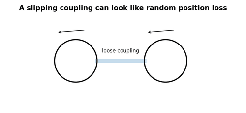
A loose encoder hub can produce position drift that mimics missing pulses. During steady motion it may follow normally, then slip during rapid acceleration, deceleration, or reversal. The electrical waveform remains clean because the encoder accurately reports its own shaft – it is the mechanical connection that is wrong.
What to Check
- Paint-mark shaft and hub.
- Check clamping screws, keys, taper locks, and hollow-shaft clamps.
- Ask whether faults occur during reversals or emergency stops.
Diagnostic Sequence
- Compare raw count to a second mechanical reference.
- Repeat the same motion at reduced acceleration.
- If error decreases sharply with lower torque, inspect coupling slip.
Common Mistakes
- Replacing electronics while ignoring witness marks.
- Overtightening tiny set screws beyond manufacturer torque.
- Using threadlocker where it prevents correct clamping or future service.
Field Rule: Clean electrical signals do not prove the encoder is following the machine.
Shaft Runout
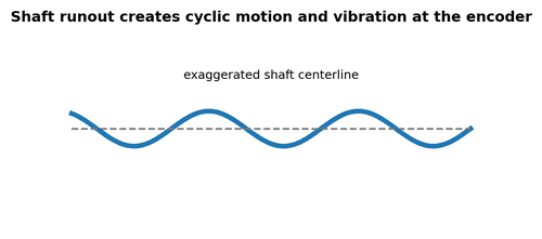
Runout means the shaft centerline moves as it rotates. Excessive runout can flex couplings, load bearings, and change encoder air gaps. The symptom may repeat once per revolution, creating a periodic speed ripple or intermittent feedback alarm at a particular angle.
What to Check
- Rotate slowly by hand under isolation and observe eccentric motion.
- Use a dial indicator where practical.
- Check bent shafts, damaged adapters, and poorly seated hollow-shaft mounts.
Diagnostic Sequence
- Correlate the fault with one revolution.
- Compare vibration with signal distortion.
- Repair the mechanical source before replacing repeated encoder failures.
Common Mistakes
- Treating every periodic electrical glitch as EMI.
- Mounting a new encoder onto a visibly damaged shaft.
- Ignoring runout after a collision or jam.
Field Rule: A once-per-revolution fault is a strong mechanical clue.
Radial and Axial Loading
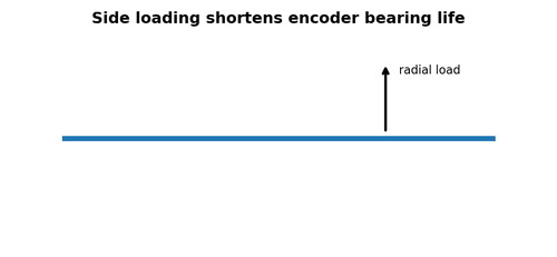
Encoder bearings are designed for limited shaft loads. Belts, rigid couplings, misalignment, or incorrect mounting can impose radial or axial force beyond the rating. Early symptoms include roughness, heat, noise, intermittent counts, and eventually total failure.
What to Check
- Check whether a belt pulley is mounted directly on an encoder not rated for it.
- Inspect axial preload from rigid couplings.
- Compare installation with the encoder bearing-load specification.
Diagnostic Sequence
- Rotate the encoder shaft gently by hand after safe isolation.
- Feel for notchiness or excessive end play.
- Investigate external loads before installing the replacement.
Common Mistakes
- Replacing the encoder without correcting the load.
- Hammering couplings onto the shaft.
- Using the encoder bearing as a machine support bearing.
Field Rule: If encoders fail repeatedly, investigate why the bearings are being overloaded.
Hollow-Shaft Encoder Mounting
Hollow-shaft encoders clamp directly onto a machine shaft and normally use a torque arm or anti-rotation bracket. Incorrect clamping, wrong shaft diameter, or a rigid torque arm can transmit runout into the encoder.
What to Check
- Check shaft diameter and fit.
- Inspect clamp ring torque.
- Verify torque arm has intended freedom and is not bent.
Diagnostic Sequence
- Mark clamp position.
- Check for fretting dust indicating motion between shaft and hub.
- Observe whether the encoder body rocks during slow rotation.
Common Mistakes
- Using an improvised rigid bracket.
- Clamping over damaged keyways or burrs.
- Ignoring shaft surface condition.
Field Rule: The anti-rotation device must restrain the body without over-constraining the bearing system.
Solid-Shaft Encoder Mounting
Solid-shaft encoders rely on a separate coupling and rigidly mounted body. Baseplate distortion, bracket flex, or bolt movement can create alignment changes that appear only under load.
What to Check
- Check bracket stiffness and bolt tightness.
- Look for cracked welds or elongated mounting holes.
- Inspect coupling gap and insertion depth.
Diagnostic Sequence
- Measure alignment unloaded and loaded if practical.
- Check whether the bracket moves during acceleration.
- Reinforce or repair the mounting before replacing electronics.
Common Mistakes
- Mounting an encoder on thin sheet metal without support.
- Bottoming the shaft inside the coupling.
- Allowing paint or burrs under the mounting face.
Field Rule: A stable reference frame is part of the measurement system.
Flexible Coupling Selection
Beam, bellows, jaw, Oldham, and other couplings have different misalignment capacity, torsional stiffness, backlash, and speed limits. A coupling that is acceptable for a slow conveyor may be unsuitable for a servo axis.
What to Check
- Identify coupling type and rating.
- Check maximum rpm and misalignment.
- Inspect for backlash and torsional windup.
Diagnostic Sequence
- Compare position response during reversal.
- Mark hubs to detect slip.
- If control tuning changed after a coupling replacement, verify stiffness and backlash.
Common Mistakes
- Selecting only by bore size.
- Assuming “flexible” means no alignment is required.
- Using a coupling with excessive backlash on precision positioning.
Field Rule: Coupling dynamics can affect both reliability and control performance.
Gear and Belt Driven Encoders
Some encoders are driven through gears, timing belts, measuring wheels, or friction rollers. In these systems the encoder may be healthy while the transmission introduces backlash, tooth damage, belt slip, or wheel slip.
What to Check
- Inspect belt tension and tooth condition.
- Check gear backlash and keys.
- Inspect measuring wheel contamination and contact pressure.
Diagnostic Sequence
- Compare encoder count to physical travel over multiple cycles.
- Test both directions to expose backlash.
- Mark belt/pulley relationships to detect intermittent slip.
Common Mistakes
- Calibrating software around a worn wheel diameter.
- Ignoring wet or oily surfaces under measuring wheels.
- Assuming a toothed belt cannot slip if teeth are damaged.
Field Rule: Troubleshoot everything between the moving product and the encoder shaft.
Environmental Sealing
Oil, coolant, water, dust, and condensation can enter through failed seals or connectors. Intermittent faults may appear after washdown, temperature cycles, or humid shutdowns.
What to Check
- Inspect IP rating against real environment.
- Check cable gland orientation and drip loops.
- Look for green corrosion, moisture tracks, and swollen seals.
Diagnostic Sequence
- Correlate faults with washdown or temperature.
- Inspect connector pins under isolation.
- Improve sealing and cable routing rather than repeatedly cleaning contacts.
Common Mistakes
- Using a higher IP-rated body with a lower-rated connector.
- Pointing cable entries upward where liquid can collect.
- Using sealants that attack cable jackets.
Field Rule: The environmental rating is only as good as the weakest connector or gland.
Temperature and Thermal Expansion
Encoder electronics, cable resistance, mechanical gaps, and brackets all change with temperature. A fault that appears after 30 minutes may be thermal rather than random.
What to Check
- Record cold and hot behavior.
- Check cabinet and machine ambient temperatures.
- Inspect mounting near brakes, ovens, motors, or steam lines.
Diagnostic Sequence
- Use a controlled warm-up while monitoring supply and signal amplitude.
- Check for connector expansion and bracket movement.
- Compare with temperature rating on the datasheet.
Common Mistakes
- Cooling only the encoder and overlooking a hot receiver module.
- Assuming room temperature reflects encoder body temperature.
- Applying heat guns directly to sealed sensors.
Field Rule: Time-to-fault is diagnostic data; record it.