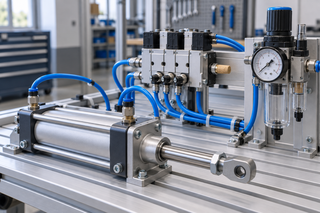
By Dovydas Kersys · Chapter 1 of 12 in Pneumatic Troubleshooting.
Before you begin: The diagrams are simplified teaching illustrations. Verify the actual machine schematic and component documentation. Isolate and control stored energy before intrusive work, and use the approved machine procedure for any energized measurements. Compressed air must not be the sole support for a load where unexpected movement could cause injury.
How Pneumatic Systems Produce Motion
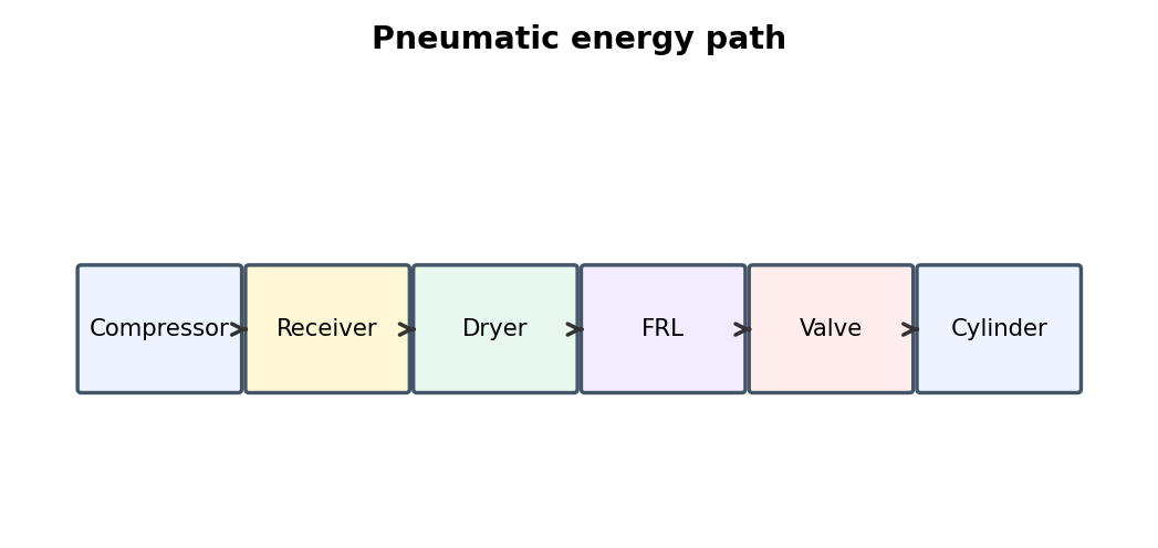
Compressed air becomes useful motion only when adequate pressure and flow reach an actuator through a correctly controlled circuit. For maintenance work, the key is to separate pressure, flow, control, actuator condition, and mechanical load instead of treating the visible cylinder as the whole system.
What to check
- Identify the air path and the component that controls the function.
- Check pressure at the point of use, not only at the compressor.
- Compare the good state/direction with the bad one.
- Use the machine schematic and actual port labels before disconnecting tubing.
Diagnostic sequence
- Make the machine safe and release hazardous stored pressure.
- Define the exact symptom and machine state.
- Verify supply, then command, then valve switching.
- Verify supply and exhaust paths at the actuator.
- Only then inspect actuator internals or machine mechanics.
Common mistakes
Replacing the cylinder first. • Changing several adjustments at once. • Testing only at idle.
FIELD RULE: Follow the air path and prove each stage before replacing parts.
Pressure vs. Flow
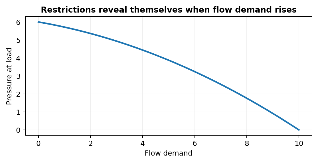
Pressure determines force potential while flow determines how quickly a volume can fill or exhaust. For maintenance work, the key is to separate pressure, flow, control, actuator condition, and mechanical load instead of treating the visible cylinder as the whole system.
What to check
- Identify the air path and the component that controls the function.
- Check pressure at the point of use, not only at the compressor.
- Compare the good state/direction with the bad one.
- Use the machine schematic and actual port labels before disconnecting tubing.
Diagnostic sequence
- Make the machine safe and release hazardous stored pressure.
- Define the exact symptom and machine state.
- Verify supply, then command, then valve switching.
- Verify supply and exhaust paths at the actuator.
- Only then inspect actuator internals or machine mechanics.
Common mistakes
Replacing the cylinder first. • Changing several adjustments at once. • Testing only at idle.
FIELD RULE: Follow the air path and prove each stage before replacing parts.
Cylinder Force and Effective Area
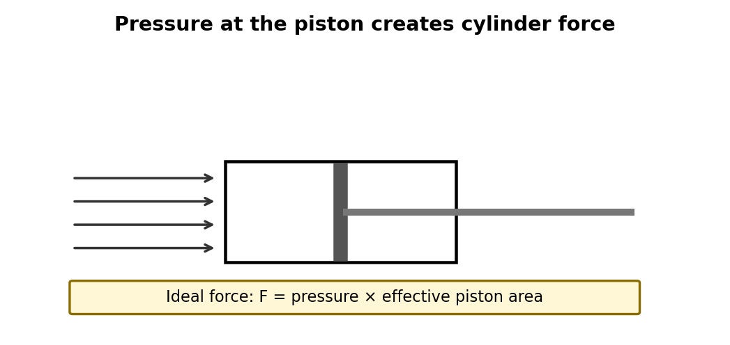
Cylinder force depends on pressure difference across the piston and effective area; retraction area is reduced by the rod. For maintenance work, the key is to separate pressure, flow, control, actuator condition, and mechanical load instead of treating the visible cylinder as the whole system.
What to check
- Identify the air path and the component that controls the function.
- Check pressure at the point of use, not only at the compressor.
- Compare the good state/direction with the bad one.
- Use the machine schematic and actual port labels before disconnecting tubing.
Diagnostic sequence
- Make the machine safe and release hazardous stored pressure.
- Define the exact symptom and machine state.
- Verify supply, then command, then valve switching.
- Verify supply and exhaust paths at the actuator.
- Only then inspect actuator internals or machine mechanics.
Common mistakes
Replacing the cylinder first. • Changing several adjustments at once. • Testing only at idle.
FIELD RULE: Follow the air path and prove each stage before replacing parts.
Air Compressibility and Stored Energy
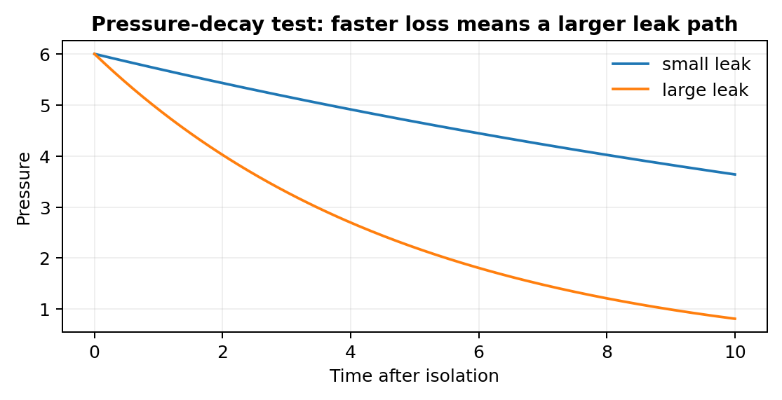
Compressed air behaves like a spring and can remain trapped behind valves or check valves after the main supply is isolated. For maintenance work, the key is to separate pressure, flow, control, actuator condition, and mechanical load instead of treating the visible cylinder as the whole system.
What to check
- Identify the air path and the component that controls the function.
- Check pressure at the point of use, not only at the compressor.
- Compare the good state/direction with the bad one.
- Use the machine schematic and actual port labels before disconnecting tubing.
Diagnostic sequence
- Make the machine safe and release hazardous stored pressure.
- Define the exact symptom and machine state.
- Verify supply, then command, then valve switching.
- Verify supply and exhaust paths at the actuator.
- Only then inspect actuator internals or machine mechanics.
Common mistakes
Replacing the cylinder first. • Changing several adjustments at once. • Testing only at idle.
FIELD RULE: Follow the air path and prove each stage before replacing parts.
Single-Acting and Double-Acting Cylinders
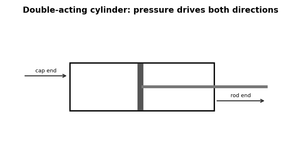
Single-acting actuators use air in one direction while double-acting cylinders use air for both extension and retraction. For maintenance work, the key is to separate pressure, flow, control, actuator condition, and mechanical load instead of treating the visible cylinder as the whole system.
What to check
- Identify the air path and the component that controls the function.
- Check pressure at the point of use, not only at the compressor.
- Compare the good state/direction with the bad one.
- Use the machine schematic and actual port labels before disconnecting tubing.
Diagnostic sequence
- Make the machine safe and release hazardous stored pressure.
- Define the exact symptom and machine state.
- Verify supply, then command, then valve switching.
- Verify supply and exhaust paths at the actuator.
- Only then inspect actuator internals or machine mechanics.
Common mistakes
Replacing the cylinder first. • Changing several adjustments at once. • Testing only at idle.
FIELD RULE: Follow the air path and prove each stage before replacing parts.
Reading Pneumatic Schematics
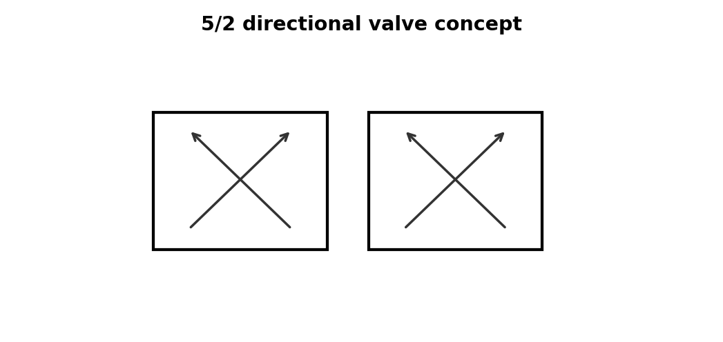
Directional-valve boxes show possible spool states and the expected pressure/exhaust routes rather than the physical internal layout. For maintenance work, the key is to separate pressure, flow, control, actuator condition, and mechanical load instead of treating the visible cylinder as the whole system.
What to check
- Identify the air path and the component that controls the function.
- Check pressure at the point of use, not only at the compressor.
- Compare the good state/direction with the bad one.
- Use the machine schematic and actual port labels before disconnecting tubing.
Diagnostic sequence
- Make the machine safe and release hazardous stored pressure.
- Define the exact symptom and machine state.
- Verify supply, then command, then valve switching.
- Verify supply and exhaust paths at the actuator.
- Only then inspect actuator internals or machine mechanics.
Common mistakes
Replacing the cylinder first. • Changing several adjustments at once. • Testing only at idle.
FIELD RULE: Follow the air path and prove each stage before replacing parts.
Port Numbers and Labels
Supply, work, exhaust, and pilot ports must be identified from markings and documentation before tubing is moved. For maintenance work, the key is to separate pressure, flow, control, actuator condition, and mechanical load instead of treating the visible cylinder as the whole system.
What to check
- Identify the air path and the component that controls the function.
- Check pressure at the point of use, not only at the compressor.
- Compare the good state/direction with the bad one.
- Use the machine schematic and actual port labels before disconnecting tubing.
Diagnostic sequence
- Make the machine safe and release hazardous stored pressure.
- Define the exact symptom and machine state.
- Verify supply, then command, then valve switching.
- Verify supply and exhaust paths at the actuator.
- Only then inspect actuator internals or machine mechanics.
Common mistakes
Replacing the cylinder first. • Changing several adjustments at once. • Testing only at idle.
FIELD RULE: Follow the air path and prove each stage before replacing parts.
Normally Open and Normally Closed
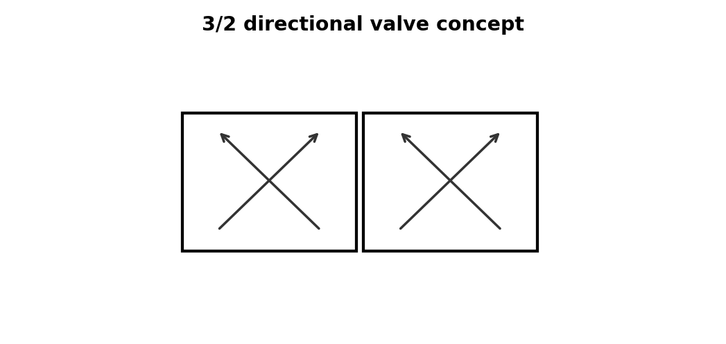
The normal state is the de-energized state and determines what a circuit does during loss of electrical command. For maintenance work, the key is to separate pressure, flow, control, actuator condition, and mechanical load instead of treating the visible cylinder as the whole system.
What to check
- Identify the air path and the component that controls the function.
- Check pressure at the point of use, not only at the compressor.
- Compare the good state/direction with the bad one.
- Use the machine schematic and actual port labels before disconnecting tubing.
Diagnostic sequence
- Make the machine safe and release hazardous stored pressure.
- Define the exact symptom and machine state.
- Verify supply, then command, then valve switching.
- Verify supply and exhaust paths at the actuator.
- Only then inspect actuator internals or machine mechanics.
Common mistakes
Replacing the cylinder first. • Changing several adjustments at once. • Testing only at idle.
FIELD RULE: Follow the air path and prove each stage before replacing parts.
Meter-In vs. Meter-Out Control
One-way flow controls create very different motion depending on which direction they throttle. For maintenance work, the key is to separate pressure, flow, control, actuator condition, and mechanical load instead of treating the visible cylinder as the whole system.
What to check
- Identify the air path and the component that controls the function.
- Check pressure at the point of use, not only at the compressor.
- Compare the good state/direction with the bad one.
- Use the machine schematic and actual port labels before disconnecting tubing.
Diagnostic sequence
- Make the machine safe and release hazardous stored pressure.
- Define the exact symptom and machine state.
- Verify supply, then command, then valve switching.
- Verify supply and exhaust paths at the actuator.
- Only then inspect actuator internals or machine mechanics.
Common mistakes
Replacing the cylinder first. • Changing several adjustments at once. • Testing only at idle.
FIELD RULE: Follow the air path and prove each stage before replacing parts.
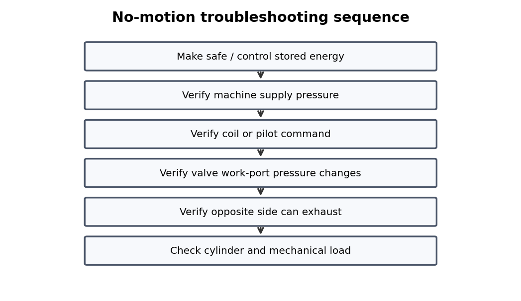
The Core Troubleshooting Sequence
A repeatable sequence prevents random regulator adjustment and unnecessary parts replacement. For maintenance work, the key is to separate pressure, flow, control, actuator condition, and mechanical load instead of treating the visible cylinder as the whole system.
What to check
- Identify the air path and the component that controls the function.
- Check pressure at the point of use, not only at the compressor.
- Compare the good state/direction with the bad one.
- Use the machine schematic and actual port labels before disconnecting tubing.
Diagnostic sequence
- Make the machine safe and release hazardous stored pressure.
- Define the exact symptom and machine state.
- Verify supply, then command, then valve switching.
- Verify supply and exhaust paths at the actuator.
- Only then inspect actuator internals or machine mechanics.
Common mistakes
Replacing the cylinder first. • Changing several adjustments at once. • Testing only at idle.
FIELD RULE: Follow the air path and prove each stage before replacing parts.
Appendix A – Quick Force Reference
- F = P × A
- Retraction uses piston area minus rod area.
- Use pressure measured at the cylinder under load.
- Allow margin for friction, acceleration, pressure drop, and mechanism geometry.
USE IT: Add machine-specific target pressures, cycle times, and test points to this page.
Continue the series
Adapted from Pneumatic Troubleshooting for Maintenance Technicians, by Dovydas Kersys. © 2026 Dovydas Kersys. Featured cover image is an AI-generated editorial illustration.