By Dovydas Kersys · Chapter 2 of 12 in Pneumatic Troubleshooting.
Before you begin: The diagrams are simplified teaching illustrations. Verify the actual machine schematic and component documentation. Isolate and control stored energy before intrusive work, and use the approved machine procedure for any energized measurements. Compressed air must not be the sole support for a load where unexpected movement could cause injury.
Compressor Capacity
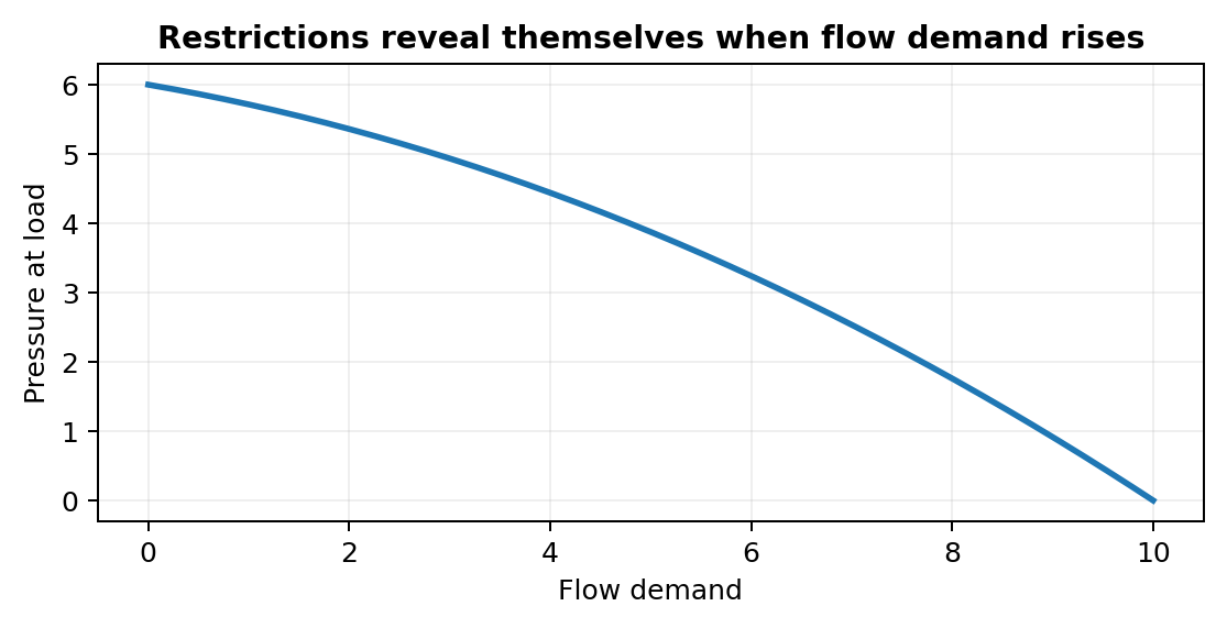
Plant pressure can collapse during high air demand when compressor capacity or storage margin is insufficient. Supply-side faults often look normal when the machine is idle because pressure has time to equalize; they become obvious only when airflow increases.
What to check
- Record static and dynamic pressure.
- Measure before and after the suspected restriction.
- Check isolation valves, filters, regulators, couplings, and shared supply lines.
- See whether other machines or simultaneous actuators change the symptom.
Diagnostic sequence
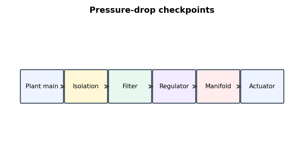
- Measure machine inlet pressure during the fault.
- If inlet pressure is low, move upstream toward the plant supply.
- If inlet is good, compare pressure across local preparation components.
- Correct the first point where pressure drops abnormally under flow.
Common mistakes
Turning the regulator higher to hide a restriction. • Trusting one panel gauge. • Ignoring shared plant demand.
FIELD RULE: Pressure drop is a flow-dependent fault; measure while air is moving.
Air Receivers
Receivers buffer short demand peaks and collect condensate but do not fix sustained undersupply. Supply-side faults often look normal when the machine is idle because pressure has time to equalize; they become obvious only when airflow increases.
What to check
- Record static and dynamic pressure.
- Measure before and after the suspected restriction.
- Check isolation valves, filters, regulators, couplings, and shared supply lines.
- See whether other machines or simultaneous actuators change the symptom.
Diagnostic sequence
- Measure machine inlet pressure during the fault.
- If inlet pressure is low, move upstream toward the plant supply.
- If inlet is good, compare pressure across local preparation components.
- Correct the first point where pressure drops abnormally under flow.
Common mistakes
Turning the regulator higher to hide a restriction. • Trusting one panel gauge. • Ignoring shared plant demand.
FIELD RULE: Pressure drop is a flow-dependent fault; measure while air is moving.
Distribution Pressure Drop
Long or undersized plant branches can show normal idle pressure but excessive drop during machine cycling. Supply-side faults often look normal when the machine is idle because pressure has time to equalize; they become obvious only when airflow increases.
What to check
- Record static and dynamic pressure.
- Measure before and after the suspected restriction.
- Check isolation valves, filters, regulators, couplings, and shared supply lines.
- See whether other machines or simultaneous actuators change the symptom.
Diagnostic sequence
- Measure machine inlet pressure during the fault.
- If inlet pressure is low, move upstream toward the plant supply.
- If inlet is good, compare pressure across local preparation components.
- Correct the first point where pressure drops abnormally under flow.
Common mistakes
Turning the regulator higher to hide a restriction. • Trusting one panel gauge. • Ignoring shared plant demand.
FIELD RULE: Pressure drop is a flow-dependent fault; measure while air is moving.
Filter Restriction
A loaded filter element can pass static pressure yet starve the machine when airflow increases. Supply-side faults often look normal when the machine is idle because pressure has time to equalize; they become obvious only when airflow increases.
What to check
- Record static and dynamic pressure.
- Measure before and after the suspected restriction.
- Check isolation valves, filters, regulators, couplings, and shared supply lines.
- See whether other machines or simultaneous actuators change the symptom.
Diagnostic sequence
- Measure machine inlet pressure during the fault.
- If inlet pressure is low, move upstream toward the plant supply.
- If inlet is good, compare pressure across local preparation components.
- Correct the first point where pressure drops abnormally under flow.
Common mistakes
Turning the regulator higher to hide a restriction. • Trusting one panel gauge. • Ignoring shared plant demand.
FIELD RULE: Pressure drop is a flow-dependent fault; measure while air is moving.
Water and Condensate
Poor moisture removal causes sticky spools, corrosion, frozen exhausts, and intermittent sensor/valve problems. Supply-side faults often look normal when the machine is idle because pressure has time to equalize; they become obvious only when airflow increases.
What to check
- Record static and dynamic pressure.
- Measure before and after the suspected restriction.
- Check isolation valves, filters, regulators, couplings, and shared supply lines.
- See whether other machines or simultaneous actuators change the symptom.
Diagnostic sequence
- Measure machine inlet pressure during the fault.
- If inlet pressure is low, move upstream toward the plant supply.
- If inlet is good, compare pressure across local preparation components.
- Correct the first point where pressure drops abnormally under flow.
Common mistakes
Turning the regulator higher to hide a restriction. • Trusting one panel gauge. • Ignoring shared plant demand.
FIELD RULE: Pressure drop is a flow-dependent fault; measure while air is moving.
Air Dryers
Refrigerated and desiccant dryers need correct drains, filters, and operating conditions to control dew point without excessive pressure loss. Supply-side faults often look normal when the machine is idle because pressure has time to equalize; they become obvious only when airflow increases.
What to check
- Record static and dynamic pressure.
- Measure before and after the suspected restriction.
- Check isolation valves, filters, regulators, couplings, and shared supply lines.
- See whether other machines or simultaneous actuators change the symptom.
Diagnostic sequence
- Measure machine inlet pressure during the fault.
- If inlet pressure is low, move upstream toward the plant supply.
- If inlet is good, compare pressure across local preparation components.
- Correct the first point where pressure drops abnormally under flow.
Common mistakes
Turning the regulator higher to hide a restriction. • Trusting one panel gauge. • Ignoring shared plant demand.
FIELD RULE: Pressure drop is a flow-dependent fault; measure while air is moving.
Regulator Setpoint and Droop
A regulator can show the correct idle pressure but sag badly under flow if it is undersized, worn, or starved upstream. Supply-side faults often look normal when the machine is idle because pressure has time to equalize; they become obvious only when airflow increases.
What to check
- Record static and dynamic pressure.
- Measure before and after the suspected restriction.
- Check isolation valves, filters, regulators, couplings, and shared supply lines.
- See whether other machines or simultaneous actuators change the symptom.
Diagnostic sequence
- Measure machine inlet pressure during the fault.
- If inlet pressure is low, move upstream toward the plant supply.
- If inlet is good, compare pressure across local preparation components.
- Correct the first point where pressure drops abnormally under flow.
Common mistakes
Turning the regulator higher to hide a restriction. • Trusting one panel gauge. • Ignoring shared plant demand.
FIELD RULE: Pressure drop is a flow-dependent fault; measure while air is moving.
Relieving vs. Non-Relieving Regulators
Some regulators vent downstream pressure when the setpoint is lowered while others leave trapped pressure in the circuit. Supply-side faults often look normal when the machine is idle because pressure has time to equalize; they become obvious only when airflow increases.
What to check
- Record static and dynamic pressure.
- Measure before and after the suspected restriction.
- Check isolation valves, filters, regulators, couplings, and shared supply lines.
- See whether other machines or simultaneous actuators change the symptom.
Diagnostic sequence
- Measure machine inlet pressure during the fault.
- If inlet pressure is low, move upstream toward the plant supply.
- If inlet is good, compare pressure across local preparation components.
- Correct the first point where pressure drops abnormally under flow.
Common mistakes
Turning the regulator higher to hide a restriction. • Trusting one panel gauge. • Ignoring shared plant demand.
FIELD RULE: Pressure drop is a flow-dependent fault; measure while air is moving.
Lubricators
Oil mist should be used only where the equipment design requires it because excess or incompatible oil can create new failures. Supply-side faults often look normal when the machine is idle because pressure has time to equalize; they become obvious only when airflow increases.
What to check
- Record static and dynamic pressure.
- Measure before and after the suspected restriction.
- Check isolation valves, filters, regulators, couplings, and shared supply lines.
- See whether other machines or simultaneous actuators change the symptom.
Diagnostic sequence
- Measure machine inlet pressure during the fault.
- If inlet pressure is low, move upstream toward the plant supply.
- If inlet is good, compare pressure across local preparation components.
- Correct the first point where pressure drops abnormally under flow.
Common mistakes
Turning the regulator higher to hide a restriction. • Trusting one panel gauge. • Ignoring shared plant demand.
FIELD RULE: Pressure drop is a flow-dependent fault; measure while air is moving.
Soft-Start and Dump Valves
A safety air-preparation valve that does not fully enable can leave the whole machine at low or zero pressure. Supply-side faults often look normal when the machine is idle because pressure has time to equalize; they become obvious only when airflow increases.
What to check
- Record static and dynamic pressure.
- Measure before and after the suspected restriction.
- Check isolation valves, filters, regulators, couplings, and shared supply lines.
- See whether other machines or simultaneous actuators change the symptom.
Diagnostic sequence
- Measure machine inlet pressure during the fault.
- If inlet pressure is low, move upstream toward the plant supply.
- If inlet is good, compare pressure across local preparation components.
- Correct the first point where pressure drops abnormally under flow.
Common mistakes
Turning the regulator higher to hide a restriction. • Trusting one panel gauge. • Ignoring shared plant demand.
FIELD RULE: Pressure drop is a flow-dependent fault; measure while air is moving.
Pressure Gauges
Panel gauges can stick, drift, or be located too far from the fault to reveal dynamic pressure loss. Good pneumatic troubleshooting depends on measurements taken at the correct location and during the failing condition, with rated test equipment and controlled stored energy.
What to check
- Use a suitable pressure/flow range.
- Install test equipment only after safe depressurization where required.
- Measure locally and dynamically.
- Record results before changing settings.
Diagnostic sequence
- Define the question the measurement must answer.
- Place the test point on each side of the suspected component.
- Run the exact failing condition.
- Compare values and move the test point based on the result.
Common mistakes
Testing only at idle. • Using an inaccurate or badly ranged gauge. • Creating a new restriction with test fittings.
FIELD RULE: Measure where the physics is happening, not where the nearest gauge happens to be.
Isolation Valves and Quick Couplers
Partially opened isolation valves and restrictive couplers are common hidden bottlenecks. Supply-side faults often look normal when the machine is idle because pressure has time to equalize; they become obvious only when airflow increases.
What to check
- Record static and dynamic pressure.
- Measure before and after the suspected restriction.
- Check isolation valves, filters, regulators, couplings, and shared supply lines.
- See whether other machines or simultaneous actuators change the symptom.
Diagnostic sequence
- Measure machine inlet pressure during the fault.
- If inlet pressure is low, move upstream toward the plant supply.
- If inlet is good, compare pressure across local preparation components.
- Correct the first point where pressure drops abnormally under flow.
Common mistakes
Turning the regulator higher to hide a restriction. • Trusting one panel gauge. • Ignoring shared plant demand.
FIELD RULE: Pressure drop is a flow-dependent fault; measure while air is moving.
Continue the series
- Previous chapter: Pneumatic Fundamentals
- Next chapter: Pneumatic Directional Valves
- Browse all Pneumatic Troubleshooting chapters
Adapted from Pneumatic Troubleshooting for Maintenance Technicians, by Dovydas Kersys. © 2026 Dovydas Kersys. Featured cover image is an AI-generated editorial illustration.