By Dovydas Kersys · Chapter 3 of 12 in Pneumatic Troubleshooting.
Before you begin: The diagrams are simplified teaching illustrations. Verify the actual machine schematic and component documentation. Isolate and control stored energy before intrusive work, and use the approved machine procedure for any energized measurements. Compressed air must not be the sole support for a load where unexpected movement could cause injury.
3/2 Directional Valves
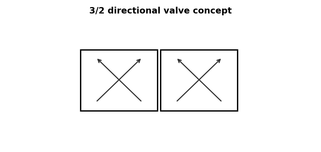
A 3/2 valve must both supply its outlet and vent it correctly when the state changes. A valve must receive a correct command, shift mechanically, route pressure to the intended work port, and provide a free exhaust path from the opposite side.
What to check
- Verify valve function and normal/center state.
- Measure coil voltage or pilot pressure while commanded.
- Check supply, work ports, and exhausts.
- Inspect manual override, spool contamination, and mufflers.
Diagnostic sequence
- Confirm electrical/air pilot command.
- Confirm the spool actually changes port pressures.
- If port pressure is wrong, troubleshoot the valve/pilot.
- If port pressure is correct, continue downstream to tubing and actuator.
Common mistakes
Assuming a click or LED proves switching. • Blocking exhaust to reduce noise. • Replacing with a visually similar but functionally different valve.
FIELD RULE: Sound and LEDs are clues; port pressure is evidence.
5/2 Directional Valves
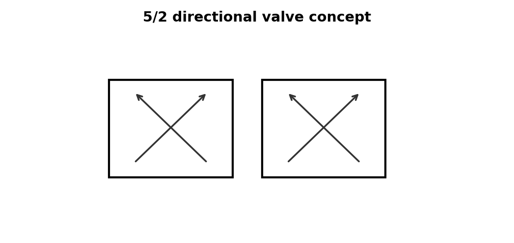
A 5/2 valve alternates supply and exhaust between the two sides of a double-acting cylinder. A valve must receive a correct command, shift mechanically, route pressure to the intended work port, and provide a free exhaust path from the opposite side.
What to check
- Verify valve function and normal/center state.
- Measure coil voltage or pilot pressure while commanded.
- Check supply, work ports, and exhausts.
- Inspect manual override, spool contamination, and mufflers.
Diagnostic sequence
- Confirm electrical/air pilot command.
- Confirm the spool actually changes port pressures.
- If port pressure is wrong, troubleshoot the valve/pilot.
- If port pressure is correct, continue downstream to tubing and actuator.
Common mistakes
Assuming a click or LED proves switching. • Blocking exhaust to reduce noise. • Replacing with a visually similar but functionally different valve.
FIELD RULE: Sound and LEDs are clues; port pressure is evidence.
5/3 Valves and Center Conditions
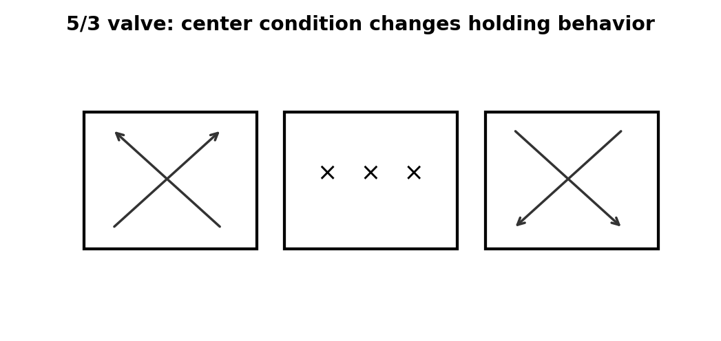
The center condition determines whether a cylinder is blocked, exhausted, or pressurized when both actuation signals are off. A valve must receive a correct command, shift mechanically, route pressure to the intended work port, and provide a free exhaust path from the opposite side.
What to check
- Verify valve function and normal/center state.
- Measure coil voltage or pilot pressure while commanded.
- Check supply, work ports, and exhausts.
- Inspect manual override, spool contamination, and mufflers.
Diagnostic sequence
- Confirm electrical/air pilot command.
- Confirm the spool actually changes port pressures.
- If port pressure is wrong, troubleshoot the valve/pilot.
- If port pressure is correct, continue downstream to tubing and actuator.
Common mistakes
Assuming a click or LED proves switching. • Blocking exhaust to reduce noise. • Replacing with a visually similar but functionally different valve.
FIELD RULE: Sound and LEDs are clues; port pressure is evidence.
Solenoid Coil Testing
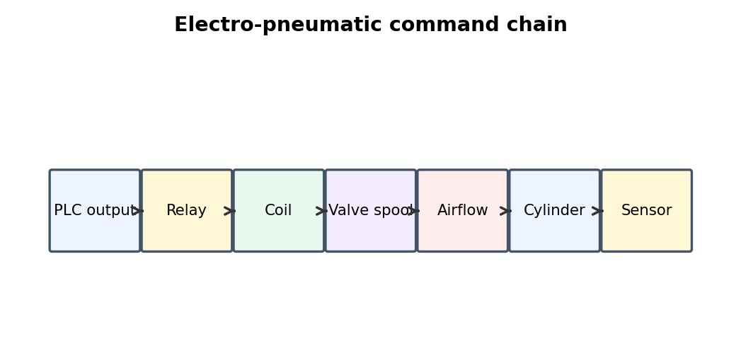
Correct voltage under load is required before a solenoid coil can be declared healthy. Electro-pneumatic faults cross the boundary between PLC logic and air power, so the command must be traced from the controller all the way to physical motion and back to sensor feedback.
What to check
- Monitor PLC output and actual field voltage.
- Measure coil voltage with the coil connected.
- Check relay/connector voltage drop.
- Verify valve work-port pressure changes and final sensor state.
Diagnostic sequence
- Start at the PLC or relay command.
- Move one stage toward the actuator until expected behavior disappears.
- Repair that stage.
- Verify final pneumatic motion and sensor feedback through repeated cycles.
Common mistakes
Assuming PLC bit ON means the coil is powered. • Assuming relay LED means the contact is good. • Changing PLC logic before proving hardware.
FIELD RULE: Trace the command chain one link at a time.
Pilot-Operated Valves
A healthy coil cannot shift the main stage if pilot pressure is missing or below the minimum. A valve must receive a correct command, shift mechanically, route pressure to the intended work port, and provide a free exhaust path from the opposite side.
What to check
- Verify valve function and normal/center state.
- Measure coil voltage or pilot pressure while commanded.
- Check supply, work ports, and exhausts.
- Inspect manual override, spool contamination, and mufflers.
Diagnostic sequence
- Confirm electrical/air pilot command.
- Confirm the spool actually changes port pressures.
- If port pressure is wrong, troubleshoot the valve/pilot.
- If port pressure is correct, continue downstream to tubing and actuator.
Common mistakes
Assuming a click or LED proves switching. • Blocking exhaust to reduce noise. • Replacing with a visually similar but functionally different valve.
FIELD RULE: Sound and LEDs are clues; port pressure is evidence.
Manual Overrides
Manual overrides can separate electrical from pneumatic faults but latching overrides can also create unexpected motion. A valve must receive a correct command, shift mechanically, route pressure to the intended work port, and provide a free exhaust path from the opposite side.
What to check
- Verify valve function and normal/center state.
- Measure coil voltage or pilot pressure while commanded.
- Check supply, work ports, and exhausts.
- Inspect manual override, spool contamination, and mufflers.
Diagnostic sequence
- Confirm electrical/air pilot command.
- Confirm the spool actually changes port pressures.
- If port pressure is wrong, troubleshoot the valve/pilot.
- If port pressure is correct, continue downstream to tubing and actuator.
Common mistakes
Assuming a click or LED proves switching. • Blocking exhaust to reduce noise. • Replacing with a visually similar but functionally different valve.
FIELD RULE: Sound and LEDs are clues; port pressure is evidence.
Sticky or Stuck Spools
Contamination, water, damaged seals, or inadequate pilot energy can make a valve shift slowly or intermittently. A valve must receive a correct command, shift mechanically, route pressure to the intended work port, and provide a free exhaust path from the opposite side.
What to check
- Verify valve function and normal/center state.
- Measure coil voltage or pilot pressure while commanded.
- Check supply, work ports, and exhausts.
- Inspect manual override, spool contamination, and mufflers.
Diagnostic sequence
- Confirm electrical/air pilot command.
- Confirm the spool actually changes port pressures.
- If port pressure is wrong, troubleshoot the valve/pilot.
- If port pressure is correct, continue downstream to tubing and actuator.
Common mistakes
Assuming a click or LED proves switching. • Blocking exhaust to reduce noise. • Replacing with a visually similar but functionally different valve.
FIELD RULE: Sound and LEDs are clues; port pressure is evidence.
Internal Valve Leakage
Worn spool or seat sealing can feed pressure into the wrong port or continuously leak to exhaust. A valve must receive a correct command, shift mechanically, route pressure to the intended work port, and provide a free exhaust path from the opposite side.
What to check
- Verify valve function and normal/center state.
- Measure coil voltage or pilot pressure while commanded.
- Check supply, work ports, and exhausts.
- Inspect manual override, spool contamination, and mufflers.
Diagnostic sequence
- Confirm electrical/air pilot command.
- Confirm the spool actually changes port pressures.
- If port pressure is wrong, troubleshoot the valve/pilot.
- If port pressure is correct, continue downstream to tubing and actuator.
Common mistakes
Assuming a click or LED proves switching. • Blocking exhaust to reduce noise. • Replacing with a visually similar but functionally different valve.
FIELD RULE: Sound and LEDs are clues; port pressure is evidence.
Clogged Mufflers
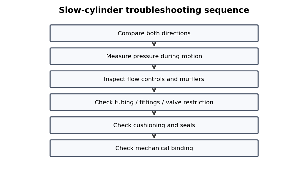
A blocked exhaust silencer can create enough backpressure to slow or stop a cylinder. A valve must receive a correct command, shift mechanically, route pressure to the intended work port, and provide a free exhaust path from the opposite side.
What to check
- Verify valve function and normal/center state.
- Measure coil voltage or pilot pressure while commanded.
- Check supply, work ports, and exhausts.
- Inspect manual override, spool contamination, and mufflers.
Diagnostic sequence
- Confirm electrical/air pilot command.
- Confirm the spool actually changes port pressures.
- If port pressure is wrong, troubleshoot the valve/pilot.
- If port pressure is correct, continue downstream to tubing and actuator.
Common mistakes
Assuming a click or LED proves switching. • Blocking exhaust to reduce noise. • Replacing with a visually similar but functionally different valve.
FIELD RULE: Sound and LEDs are clues; port pressure is evidence.
Valve Manifolds
Shared pressure and exhaust galleries mean one restriction can affect several valve stations at once. A valve must receive a correct command, shift mechanically, route pressure to the intended work port, and provide a free exhaust path from the opposite side.
What to check
- Verify valve function and normal/center state.
- Measure coil voltage or pilot pressure while commanded.
- Check supply, work ports, and exhausts.
- Inspect manual override, spool contamination, and mufflers.
Diagnostic sequence
- Confirm electrical/air pilot command.
- Confirm the spool actually changes port pressures.
- If port pressure is wrong, troubleshoot the valve/pilot.
- If port pressure is correct, continue downstream to tubing and actuator.
Common mistakes
Assuming a click or LED proves switching. • Blocking exhaust to reduce noise. • Replacing with a visually similar but functionally different valve.
FIELD RULE: Sound and LEDs are clues; port pressure is evidence.
Check Valves
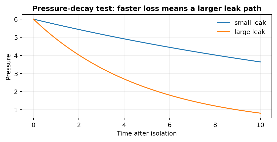
A check valve can trap pressure, restrict reverse flow, or leak when contamination damages the seat. A valve must receive a correct command, shift mechanically, route pressure to the intended work port, and provide a free exhaust path from the opposite side.
What to check
- Verify valve function and normal/center state.
- Measure coil voltage or pilot pressure while commanded.
- Check supply, work ports, and exhausts.
- Inspect manual override, spool contamination, and mufflers.
Diagnostic sequence
- Confirm electrical/air pilot command.
- Confirm the spool actually changes port pressures.
- If port pressure is wrong, troubleshoot the valve/pilot.
- If port pressure is correct, continue downstream to tubing and actuator.
Common mistakes
Assuming a click or LED proves switching. • Blocking exhaust to reduce noise. • Replacing with a visually similar but functionally different valve.
FIELD RULE: Sound and LEDs are clues; port pressure is evidence.
Quick Exhaust Valves
Quick exhaust devices speed motion by venting near the cylinder but can become leaking or restricted failure points. A valve must receive a correct command, shift mechanically, route pressure to the intended work port, and provide a free exhaust path from the opposite side.
What to check
- Verify valve function and normal/center state.
- Measure coil voltage or pilot pressure while commanded.
- Check supply, work ports, and exhausts.
- Inspect manual override, spool contamination, and mufflers.
Diagnostic sequence
- Confirm electrical/air pilot command.
- Confirm the spool actually changes port pressures.
- If port pressure is wrong, troubleshoot the valve/pilot.
- If port pressure is correct, continue downstream to tubing and actuator.
Common mistakes
Assuming a click or LED proves switching. • Blocking exhaust to reduce noise. • Replacing with a visually similar but functionally different valve.
FIELD RULE: Sound and LEDs are clues; port pressure is evidence.
Flow-Control Adjustment
A flow control that was moved during maintenance can create slow motion, hard impact, or PLC timeouts. A valve must receive a correct command, shift mechanically, route pressure to the intended work port, and provide a free exhaust path from the opposite side.
What to check
- Verify valve function and normal/center state.
- Measure coil voltage or pilot pressure while commanded.
- Check supply, work ports, and exhausts.
- Inspect manual override, spool contamination, and mufflers.
Diagnostic sequence
- Confirm electrical/air pilot command.
- Confirm the spool actually changes port pressures.
- If port pressure is wrong, troubleshoot the valve/pilot.
- If port pressure is correct, continue downstream to tubing and actuator.
Common mistakes
Assuming a click or LED proves switching. • Blocking exhaust to reduce noise. • Replacing with a visually similar but functionally different valve.
FIELD RULE: Sound and LEDs are clues; port pressure is evidence.
Local Pressure-Reducing Valves
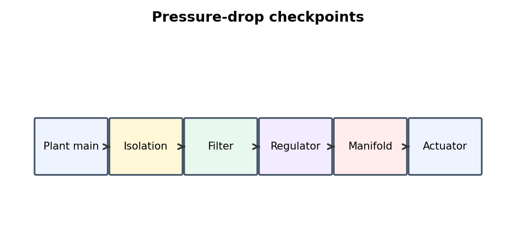
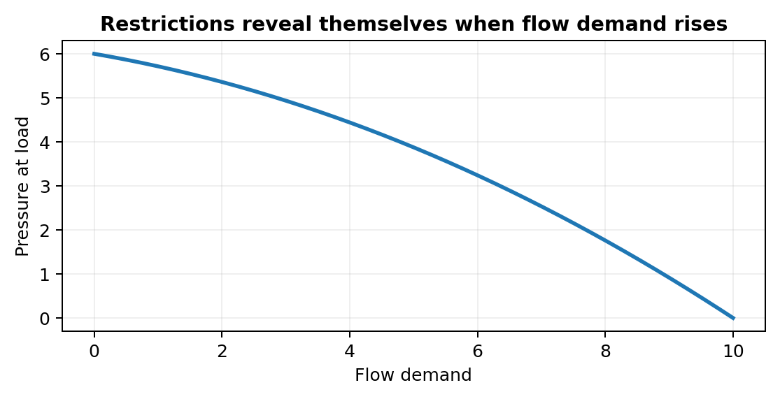
Hidden branch regulators can make one clamp or gripper weak even when the main machine pressure is normal. Supply-side faults often look normal when the machine is idle because pressure has time to equalize; they become obvious only when airflow increases.
What to check
- Record static and dynamic pressure.
- Measure before and after the suspected restriction.
- Check isolation valves, filters, regulators, couplings, and shared supply lines.
- See whether other machines or simultaneous actuators change the symptom.
Diagnostic sequence
- Measure machine inlet pressure during the fault.
- If inlet pressure is low, move upstream toward the plant supply.
- If inlet is good, compare pressure across local preparation components.
- Correct the first point where pressure drops abnormally under flow.
Common mistakes
Turning the regulator higher to hide a restriction. • Trusting one panel gauge. • Ignoring shared plant demand.
FIELD RULE: Pressure drop is a flow-dependent fault; measure while air is moving.
Continue the series
- Previous chapter: Pneumatic Air Supply And Preparation
- Next chapter: Pneumatic Cylinders And Actuators
- Browse all Pneumatic Troubleshooting chapters
Adapted from Pneumatic Troubleshooting for Maintenance Technicians, by Dovydas Kersys. © 2026 Dovydas Kersys. Featured cover image is an AI-generated editorial illustration.