An electromagnetic flow meter, also called a mag meter, is a device used to measure the flow of conductive liquids inside a pipe.
It is commonly used in:
Water systems
Wastewater plants
Chemical processing
Food and beverage production
Industrial process lines
Cooling circuits
Dosing systems
Utility flow measurement
The main idea is simple:
A conductive liquid moves through a magnetic field, and this movement creates a small electrical voltage.
The faster the liquid flows, the higher the voltage becomes.
The flow meter detects this voltage and converts it into a flow value.
What Is an Electromagnetic Flow Meter?
An electromagnetic flow meter is a type of flow sensor used to measure liquid flow without using moving parts.
Unlike a mechanical flow meter, it does not use a turbine, paddle wheel, or rotating element.
Instead, it uses an electromagnetic measurement principle.
This makes it useful for many industrial applications because there are no moving parts inside the measuring pipe that can wear out.
Electromagnetic flow meters are especially useful for conductive liquids such as:
Water
Wastewater
Process liquids
Chemical mixtures
Slurries
Cleaning liquids
Food-grade liquids
Cooling water
However, they normally do not work with non-conductive liquids such as oil, pure demineralized water, or many hydrocarbons.
The liquid must have enough electrical conductivity for the meter to measure properly.
Measurement Principle of an Electromagnetic Flow Meter
The measurement principle is based on Faraday’s law of electromagnetic induction.
This law says that when a conductive material moves through a magnetic field, an electrical voltage is generated.
In an electromagnetic flow meter, the conductive material is the liquid flowing through the pipe.
Inside the sensor, coils create a magnetic field across the measuring tube.
The liquid flows through this magnetic field.
As the conductive liquid moves through the magnetic field, charge carriers inside the liquid are affected. This creates a small voltage.
This voltage is measured by electrodes installed in the measuring pipe.
Simple Explanation
The process looks like this:
Magnetic coils create a magnetic field.
Conductive liquid flows through the magnetic field.
Movement of the liquid creates an induced voltage.
Electrodes detect this voltage.
The transmitter converts the signal into a flow rate.
The important rule is:
Higher flow velocity = higher induced voltage.
So, when the liquid moves faster, the flow meter detects a stronger voltage signal.
When the liquid moves slower, the voltage signal becomes smaller.
Main Components of an Electromagnetic Flow Meter
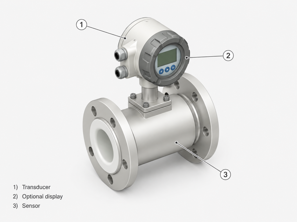
A typical electromagnetic flow meter has two main parts:
Sensor
Transmitter
Some models also include a display, communication output, relay outputs, or local configuration buttons.
1. Flow Sensor
The sensor is the part installed directly into the pipe.
It contains the measuring tube, magnetic coils, electrodes, and pipe lining.
The sensor is responsible for detecting the voltage created by the moving conductive liquid.
The sensor is usually installed inline with the process pipe, which means the liquid flows directly through the measuring tube.
The sensor must match the process conditions, including:
Pipe size
Flow rate
Liquid type
Pressure
Temperature
Chemical compatibility
Conductivity
Installation position
2. Transmitter
The transmitter receives the small signal from the sensor and converts it into usable flow information.
It can calculate and display values such as:
Instant flow rate
Total flow volume
Positive flow total
Reverse flow total
Net flow total
Alarm status
Output signals
The transmitter may be mounted directly on the sensor or installed remotely, depending on the application.
3. Display
Many electromagnetic flow meters include a local display.
The display is useful because it allows the operator or technician to see the flow value directly at the process line.
Depending on the model, the display may show:
Flow rate
Totalized flow
Positive flow counter
Negative flow counter
Net flow counter
Units
Alarms
Relay status
Graphical flow indication
Device tag or label
This makes setup and troubleshooting much easier.
Typical Display Areas
A flow meter display is often divided into several areas.
The exact design depends on the manufacturer, but the general idea is usually similar.
Status Area
The status area shows important device information.
This may include:
Alarm symbols
Error messages
Relay status
Communication status
Output status
Device warning icons
This part of the display is useful during troubleshooting because it can quickly show if the meter has a problem.
Main Measurement Area
The main section usually shows the most important process value.
For example:
Flow rate in liters per minute
Flow rate in cubic meters per hour
Total volume
Net volume
Positive total
Negative total
The user can often choose which value should be shown as the main value.
Additional Information Area
Some displays also have an extra area for additional information.
This may show:
Measurement units
Tag number
Device label
Bar graph
Flow percentage
Secondary counter
Small trend indication
This helps the operator understand not only the number, but also the flow condition.
Pipe Lining in Electromagnetic Flow Meters
The measuring tube inside an electromagnetic flow meter usually has a lining material.
This lining separates the metal body of the sensor from the process liquid.
Choosing the correct lining is very important.
The lining must be suitable for the liquid, pressure, temperature, and process conditions.
Common lining materials may include:
PTFE
PFA
Rubber
Hard rubber
Soft rubber
Ceramic
Other chemical-resistant materials
The correct lining depends on the application.
What Affects Lining Selection?
When selecting a lining material, consider:
Liquid type
Chemical aggressiveness
Abrasive particles
Solids in the liquid
Process temperature
Process pressure
Cleaning method
Food or hygienic requirements
Risk of coating or buildup
Pipe size
For example, a clean water application may not need the same lining as an abrasive slurry or aggressive chemical.
Using the wrong lining can cause damage, swelling, chemical attack, measurement problems, or early sensor failure.
Electrode Material
Electrodes are used to detect the induced voltage created by the moving liquid.
Because electrodes touch the process liquid, their material must also be selected correctly.
Common electrode materials may include:
Stainless steel
Hastelloy
Titanium
Tantalum
Platinum alloys
Other corrosion-resistant materials
The correct choice depends on the chemical properties of the liquid.
For simple water applications, standard stainless steel may be enough.
For aggressive chemicals, a more resistant electrode material may be required.
Choosing the Correct Flow Meter Size
One of the most important steps is choosing the correct nominal diameter of the flow meter.
The flow meter size is usually selected based on:
Existing pipe size
Expected minimum flow
Expected normal flow
Expected maximum flow
Flow velocity
Pressure loss
Allowed pipe reduction
Process requirements
In many cases, the flow meter size is close to the existing pipe size.
However, sometimes the best sensor size is slightly smaller than the pipe size.
This is done to keep the liquid velocity inside the correct measurement range.
Why Flow Velocity Matters
Electromagnetic flow meters measure flow based on velocity.
If the velocity is too low, the signal may become weak and unstable.
If the velocity is too high, pressure loss, noise, or wear may increase.
That is why the flow velocity should normally stay within the recommended range from the flow meter manufacturer.
A common practical goal is to choose a meter size that gives a stable velocity during normal operation.
Nominal Diameter
The nominal diameter is usually shown as DN size, for example:
DN 10
DN 25
DN 50
DN 100
DN 150
The DN size should be chosen based on the process pipe and flow conditions.
Small pipes are used for low flow rates.
Large pipes are used for higher flow rates.
But the important point is not only pipe size. The flow velocity must also make sense for the application.
What If the Flow Meter Size Is Different From the Pipe Size?
Sometimes the calculated best flow meter size does not match the existing pipe.
For example, the pipe may be DN 80, but the best measurement range may be achieved with a DN 65 sensor.
In this case, reducers or conical adapters can be used.
However, this must be done carefully.
When reducing the pipe diameter, you must consider:
Pressure loss
Flow profile
Installation space
Reducer angle
Process limitations
Risk of turbulence
Manufacturer installation rules
A smooth reducer is usually better than a sharp sudden reduction.
If the reduction is too aggressive, it can disturb the flow and affect measurement accuracy.
Pressure Loss
When the pipe diameter is reduced, the liquid velocity increases.
This can cause pressure loss.
Pressure loss is important because it may affect pumps, process performance, and the overall system.
Before using a smaller flow meter size, always check whether the system can handle the additional pressure drop.
In real projects, pressure loss should be checked using manufacturer charts, software, or engineering calculations.
Flow Direction and Reverse Flow
Many electromagnetic flow meters can measure flow direction.
This means they can detect:
Forward flow
Reverse flow
Net flow
This is useful in systems where flow may sometimes reverse.
For example, a display or transmitter may show:
Positive totalizer
Negative totalizer
Net totalizer
Positive flow means flow in the normal configured direction.
Negative flow means flow in the opposite direction.
Net flow is the difference between positive and negative flow.
This is useful in process systems, filling systems, dosing lines, and some water applications.
Output Signals and Communication
Electromagnetic flow meters usually provide output signals for automation systems.
Common outputs include:
4–20 mA analog output
Pulse output
Frequency output
Relay output
Digital communication
Modbus
HART
PROFINET
IO-Link
EtherNet/IP
The exact options depend on the meter model.
In automation, the flow meter may be connected to:
PLC
DCS system
HMI
SCADA system
Data logger
Pump controller
Batch controller
For example, a PLC may read the 4–20 mA signal as flow rate and use it for control or monitoring.
Example: Flow Meter Connected to a PLC
A simple setup could look like this:
Flow meter installed in the pipe.
Transmitter converts the sensor signal into 4–20 mA.
PLC analog input reads the 4–20 mA signal.
PLC scales the signal into liters per minute.
HMI displays the flow rate.
PLC uses the flow value for control or alarm logic.
This is very common in industrial automation.
The PLC does not need to understand the magnetic measurement principle. It only needs a clean signal from the transmitter.
Advantages of Electromagnetic Flow Meters
Electromagnetic flow meters have several strong advantages.
1. No Moving Parts
There is no rotating turbine, paddle, or mechanical element inside the pipe.
This reduces mechanical wear and makes the meter suitable for many industrial liquids.
2. Good for Dirty or Conductive Liquids
Mag meters are often used for water, wastewater, process liquids, and some slurries.
They can work well where mechanical meters may wear or clog.
3. Low Pressure Loss
Because the measuring tube is usually open and unobstructed, pressure loss can be low when the meter is correctly sized.
4. Measures Forward and Reverse Flow
Many electromagnetic flow meters can detect flow direction.
This is useful for systems where reverse flow can occur.
5. Good Accuracy for Conductive Liquids
When installed correctly and used with the correct liquid, electromagnetic flow meters can provide reliable and accurate flow measurement.
Limitations of Electromagnetic Flow Meters
Electromagnetic flow meters are very useful, but they are not suitable for every application.
1. The Liquid Must Be Conductive
This is the most important limitation.
If the liquid is not conductive enough, the meter cannot generate a usable measurement signal.
Mag meters are usually not suitable for:
Oils
Fuels
Gases
Steam
Pure hydrocarbons
Very low-conductivity liquids
Always check the minimum conductivity requirement.
2. Not for Gas or Steam
Electromagnetic flow meters are made for conductive liquids.
They do not measure gas or steam flow.
3. Installation Matters
The meter needs proper installation.
Poor installation can cause unstable readings.
Common problems include:
Partially filled pipe
Air bubbles
Turbulence
Bad grounding
Poor electrode contact
Incorrect mounting position
Insufficient straight pipe length
4. Lining and Electrodes Must Match the Medium
If the wrong materials are selected, the flow meter can be damaged by the process liquid.
This is especially important with chemicals, abrasive liquids, and high-temperature applications.
Installation Tips for Electromagnetic Flow Meters
To get reliable measurement, follow the manufacturer’s installation instructions.
General good practices include:
Install the meter in a full pipe.
Avoid mounting where air can collect.
Avoid partially filled pipe conditions.
Use proper grounding.
Follow straight pipe recommendations.
Install away from strong vibration when possible.
Make sure the arrow matches flow direction.
Choose correct lining and electrode material.
Avoid strong electromagnetic interference.
Check process temperature and pressure limits.
A magnetic flow meter can be very accurate, but only if it is installed correctly.
Common Problems and Troubleshooting
No Flow Reading
Possible causes:
Pipe is empty
Liquid is not conductive
No power to transmitter
Wrong wiring
Faulty output signal
Electrodes not contacting liquid
Incorrect setup
Unstable Flow Reading
Possible causes:
Air bubbles
Partially filled pipe
Turbulence
Poor grounding
Electrical noise
Bad electrode contact
Flow too low
Incorrect pipe size
Flow Value Too High or Too Low
Possible causes:
Wrong pipe diameter setting
Incorrect scaling in PLC
Wrong units
Poor installation
Wrong calibration settings
Partially filled pipe
Flow profile disturbance
PLC Shows Wrong Flow
Possible causes:
4–20 mA scaling error
Wrong analog input range
Incorrect engineering units
Wrong maximum flow value
Cable wiring issue
Signal noise
Bad common/ground reference
When troubleshooting, always check both sides:
Flow meter configuration
PLC analog scaling
Many flow measurement problems are not caused by the sensor itself, but by incorrect scaling in the PLC or HMI.
How to Choose an Electromagnetic Flow Meter
Before choosing a mag meter, check:
Liquid conductivity
Flow range
Pipe size
Minimum and maximum flow
Process pressure
Process temperature
Lining material
Electrode material
Output signal
Display requirement
Communication protocol
Power supply
Installation space
Hygienic requirements
Chemical compatibility
Accuracy requirement
Grounding requirement
Certification requirements
For automation projects, also check how the meter will connect to the control system.
For example:
Do you need 4–20 mA?
Do you need pulse output?
Do you need Modbus?
Do you need alarm relays?
Do you need local display?
Do you need totalizer values?
Simple Example
Imagine a water line where you need to measure flow into a tank.
The liquid is conductive, so an electromagnetic flow meter is suitable.
The sensor is installed inline in the pipe.
The transmitter sends a 4–20 mA signal to the PLC.
The PLC scales the signal to show flow in liters per minute.
The HMI displays:
Current flow rate
Total volume
High flow alarm
Low flow alarm
The operator can see the flow, and the PLC can use the value for control.
This is a very common industrial setup.
Final Thoughts
An electromagnetic flow meter measures the flow of conductive liquid using Faraday’s law of electromagnetic induction.
The basic idea is:
A magnetic field is created inside the measuring tube.
A conductive liquid flows through the magnetic field.
A small voltage is generated.
Electrodes detect this voltage.
The transmitter converts it into flow rate and volume.
The faster the liquid flows, the higher the induced voltage becomes.
Electromagnetic flow meters are widely used because they have no moving parts, can measure many conductive liquids, and are practical for industrial automation.
The most important things to remember are:
The liquid must be conductive.
The pipe must be full.
The meter must be sized correctly.
The lining and electrodes must match the medium.
The output must be scaled correctly in the PLC or control system.
For PLC and automation learning, electromagnetic flow meters are a great example of how physics, sensors, transmitters, and control systems work together in real industrial processes.